Table of Contents
hide
Introduction
- UML (Unified Modeling Language) is a standard notation for modeling software systems.
Definition
- UML stands for Unified Modeling Language, which is a standard visual modeling language used in software engineering to describe, design, and document software systems.
Characteristics
- UML provides a set of graphical notations to represent different aspects of a software system, such as its structure, behavior, and interactions.
- UML diagrams are used throughout the software development lifecycle to aid in the communication, design, and documentation of software systems.
- UML can be used by software developers, architects, and other stakeholders to understand and communicate complex systems in a standardized way.
- UML diagrams are an effective way to communicate and document software systems, allowing designers, developers, and stakeholders to better understand the system being modeled.
Types of UML
- There are several types of UML diagrams, each representing a specific aspect of the system being modeled.
- Here are some of the most common types of UML diagrams:
-
Use Case Diagrams:
-
These diagrams describe the interactions between a system and its external actors (such as users or other systems) and represent the system’s functionalities.
-
This diagram shows the functional requirements of the system by depicting the actors, use cases, and the relationships between them.
-
-
Class Diagrams:
- This diagram shows the static structure of the system by depicting the classes, attributes, operations/methods, and their relationships between objects.
-
Sequence Diagrams:
-
These diagrams show the interactions between different parts of a system’s objects in a time-ordered manner and illustrate how these objects collaborate with each other to achieve specific tasks.
- This diagram shows the interaction between objects in a particular scenario by depicting the sequence of messages exchanged between them.
-
-
Activity Diagrams:
-
These diagrams describe the workflows(flow of activities) and processes of a system and represent the sequence of activities performed by different components or actors in the system.
- This diagram shows the flow of activities or processes in a particular scenario by depicting the activities, decision points, and branching paths.
-
-
State Machine Diagrams:
-
These diagrams show the detailed transitions between states of an object or system and represent how it responds to events and changes over time.
-
-

-
-
Object Interaction Diagram:
-
-
-
- Object Interaction Diagram illustrates the interaction between various objects of an object-oriented system.
- This diagram consists of directed lines between clients and servers. Each box contains the name of the object. This diagram also shows conditions for messages to be sent to other objects. The vertical distance is used to show the life of an object.
-

-
-
Component Diagram:
- This diagram shows the physical components of the system and their relationships, including libraries, executables, and source files.
-
Deployment Diagram:
-
This diagram shows how the software system is deployed on hardware components, such as servers, networks, and devices.
-
-
-
-
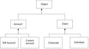
Inheritance Diagram
- An inheritance diagram is a design diagram that primarily documents the inheritance relationships between classes and interfaces in object-oriented modeling.
- The standard notation consists of one box for each class. The boxes are arranged in a hierarchical tree according to their inheritance characteristics. Each class box includes the class name, its attributes, and its operations.
-
-
-
Aggregation Diagram
-
-
-
- An aggregation diagram shows relationships among objects.
- When a class is formed as a collection of other classes, it is called an aggregation relationship between these classes. Each module will be represented by its name. The relationship will be indicated by a directed line from container to container. The directed line is labeled with the cardinality of the relationship.
- It describes “has a” relationship between two classes (a circle has a shape).
-

Use of UML
- UML diagrams are used to visualize, design, and document the architecture of a software system.
![]()
0 Comments