Introduction
- An arithmetic logic unit (ALU) is a crucial part of a CPU.
- An Arithmetic Logic Unit (ALU) is a critical component of the central processing unit (CPU) in computers.
Definition
- An arithmetic logic unit (ALU) is an execution unit and an important part of a CPU that does simple as well as complex arithmetic, logic, and shift operations in the form of binary arithmetic and boolean algebra.
Features
- It handles all arithmetic and logical operations such as addition, subtraction, multiplication, division, AND, OR, NOT operations, etc.
- The complexity of an ALU depends on the type of instruction set used in it. The design and organization of an ALU can vary based on the complexity and functionality required. The design can range from simple (for basic microcontrollers) to highly complex (for modern processors with multiple functional units).
-
The simple type of ALUs can be constructed for fixed-point numbers.
- In high-performance CPUs, ALUs may be pipelined to increase throughput.
- Multiple ALUs may operate in parallel(parallelism) to handle vector operations (e.g., SIMD).
- There may be separate units integrated with ALU for floating-point arithmetic operations(Floating Point Unit[FPU]).
-
Bit Slice ALUs :
- It is a feasible product of ALU for manufacture.
- When an ALU is constructed simply of smaller size with less complexity for 4 or 8 bits fixed point data and is created on a single IC chip. Later, these 4 or 8-bit ALU chips, in combination, can make 16, 32, 64-bit array-like circuits for complex data manipulation. These are called bit-slice ALUs.
- The basic advantage of Bit Slice ALUs is that these ALUs can be constructed for a desired word size.
Components of an ALU
-
Inputs:
- Operands: It is binary numbers to be processed.
- Control Signals: It determines the specific operation to be performed.
-
Outputs:
- Result: This is the output of the arithmetic or logic operation.
- Status Flags: These indicate various conditions of flag registers (e.g., zero, carry, overflow).
Basic Functions of an ALU
-
Arithmetic Operations:
- Addition
- Subtraction
- Increment/Decrement
- Multiplication (in more complex ALUs)
- Division (in more complex ALUs)
-
Logic Operations:
- AND
- OR
- XOR
- NOT
- NAND
- NOR
-
Shift Operations:
- Logical Shift Left/Right
- Arithmetic Shift Left/Right
- Rotate Left/Right
ALU Organization
-
Arithmetic Unit:
- Adders: Implement addition and subtraction (using two’s complement).
- Half Adders and Full Adders: Building blocks for adders.
- Ripple Carry Adders: Simple design but slow for large bit-widths.
- Carry Look-Ahead Adders: Faster, used in more advanced ALUs.
- Multiplier: For multiplication operations, in the latest CPU.
- Divider: For division operations (if included), in the latest CPU.
- Adders: Implement addition and subtraction (using two’s complement).
-
Logic Unit:
- Implements basic logic gates and operations.
- Can include more complex gates based on design requirements.
-
Shifter/Rotator:
- Shifts bits left or right.
- Can perform logical, arithmetic, and rotate shifts.
-
Multiplexer (MUX):
- Selects the output from the Arithmetic or Logic unit based on control signals.
-
Control Unit:
- Generates control signals to select the required operation.
- Decodes instruction codes to control the ALU operations.
- Status Flags:
ALUs typically include flags to indicate the status of the result:
-
- Zero (Z): Set if the result is zero.
- Carry (C): Set if there’s a carry-out from the most significant bit.
- Overflow (V): Set if the arithmetic operation results in an overflow.
- Negative (N): Set if the result is negative (in signed operations).
Explanation of an ALU Operation
Consider and suppose a simple ALU performing addition:-
- Operands: A = 1101, B = 1011
- Control Signal: Generates & indicates addition
- Adder:
- Sum = A + B = 1101 + 1011 = 11000
- Carry = 1 (overflow into the 5th bit)
- Result: 1000 (after dropping the carry bit, because of unsigned addition)
- Status Flags:
- Zero = 0 (result is not zero)
- Carry = 1 (there was a carry-out)
- Overflow = 0 (no overflow for unsigned addition)
- Negative = 0 (result is not negative)
Architecture of ALU
- An ALU consists of several Logic circuits in certain predefined order that perform data processing micro-operations.
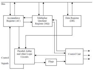
- The structure of a Fixed point Arithmetic logic unit has three registers AC, MQ, and DR for data storage. We here assume that all are equal to one word each. Here, Parallel adders and other logic circuits (these are the arithmetic, logic circuits) have two inputs and only one output in this diagram.
- It implies that any ALU operation at most can have two input values and will generate a single output along with the other status bits.
- Here, the two inputs are AC and DR registers, while the output is the AC register. AC and MQ registers are generally used as a single AC.MQ register. This register is capable of left or right-shift operations.
- Some of the micro-operations that can be defined on this ALU are: –
Addition : AC ← AC + DR
Subtraction : AC ← AC – DR
AND : AC ← AC ^ DR
OR : AC ← AC v DR
Exclusive OR : AC ← AC (+) DR
NOT : AC ← AC - This type of ALU organization does multiplication and division operations using shift-add/subtract operations. Here, the MQ (Multiplier-Quotient register) is a special register used for the implementation of multiplication and division. One such type of algorithm is Booth’s algorithm which talks about the mechanism of multiplication and division.
- During multiplication or division operations, the DR register stores the multiplicand or divisor output respectively. The result of multiplication or division on applying/using certain algorithms can finally be obtained in AC.MQ register combination. These operations can be represented as: –
Multiplication : AC.MQ ← DR × MQ
Division : AC.MQ ← MQ ÷ DR - DR is another important register, which is used for storing the second operand i.e., it acts as a buffer register, which stores the data brought from the memory for an instruction. In machines where we have general-purpose registers any of the registers can be utilized as AC, MQ, and DR.
![]()
0 Comments