Introduction
- Micro Operation is the functionality of ALU & the control unit of CPU that describes how an instruction is executed.
- It is the key concept of instruction execution.
- A digital system performs a sequence of micro-operations on data stored in registers or memory.
- Micro-operations form the basis of executing complex instructions within the CPU. Understanding these operations helps in grasping how a CPU processes instructions, manages data and performs computations.
- They are fundamental in the design and operation of computer processors.
Definition
- A micro-operation is an elementary operation performed during one clock pulse inside the ALU and Control unit of the CPU.
- Micro-operations are the fundamental operations performed by the CPU’s control unit to execute an instruction.
Features
- An instruction is a binary code specifying a definite sequence of micro-operations to perform a specific function.
- Micro-operations are smaller steps that break down the instruction cycle into manageable actions.
- The specific sequence of micro-operations performed is predetermined for an instruction.
- Micro-instruction :
- Micro-operation is executed with the help of several micro-instructions.
- The micro-instructions are stored in the control unit’s memory.
- The address register for the control memory contains the address of the next instruction that is to be read.
- The control memory Buffer Register receives the micro-instruction that has been read.
- A micro-instruction execution primarily involves the generation of desired control signals and signals used to determine the next micro-instruction to be executed.
- The sequencing logic section loads the control memory address register. It also issues a read command to control memory.
- The execute cycle steps of micro-operations are different for all instructions in addition the addressing mode may be different. All such information generally is dependent on the opcode of the instruction Register (IR).
- For example – The micro-operation can be understood with the help of an example of a program segment. For this, suppose we have a C program segment say sum = sum + 7. This program segment will first be converted to equivalent assembly program as: –
Step 1: Move data from memory location sum to register say R1 (LOAD R1, sum).
Step 2: Now, add an immediate operand value(7) to register (R1) and then store the results in R1 (ADD R1, 7).
Step 3: Transfer & store the result from register R1 to memory location sum (STORE sum, R1).
Thus, the above machine instructions are responsible (which may vary from machine to machine) for executing a simple program segment of a C statement.
Thus, from the above example, we can see that these machine statements are executed with the help of micro-operations which are explained in detail in the following execution steps:-
(a)Fetch the instructions
-
- Pass the address of the Program Counter (PC) to the Memory Address Register (MAR).
- Issue the memory read operation to fetch instructions in the Buffer Register for data, such as MBR.
- Increment Program Counter to refer to the next instruction in sequence and bring instruction to the Instruction Register (IR).
(b)Execute the instruction
-
- Decode the instruction to confirm the operation.
- As one of the operands is already available in the R1 register and the second operand is immediate (say 7 here) so fetch operand step is not required here. The immediate operand is available in the address part of the instruction.
- Perform the ALU-based addition with R1 and buffer register, and store the result in R1.
Thus, we may have to execute the instruction in several steps and each micro-operation can be completed in one clock period, although some micro-operations also require memory read/write that may take more time.
Types of Micro Operations
(1) Register/Data transfer micro-operations
(2) Arithmetic micro-operations
(3) Logic micro-operations
(4) Shift micro-operations
The above micro-operations performed by a CPU can be broadly classified into two groups for simplicity –
(a) Micro-operations for Data transfer:-
-
- To move data from register-register, register-memory, I/O-register, etc as per need of the operations.
(b) Micro-operations for performing Mathematical operations:-
-
- This includes arithmetic, logic, and shift operations mainly.
- These micro-operations involve the use of registers for input and output.
(1) Register/Data Transfer Micro-Operations :
- These operations move data from one location to another within the CPU or between the CPU and memory or I/O devices.
- This micro-operation simply transfers binary information from one register to another. For this, all the registers are connected using a common Bus that transfers information from one register to another. The content of the selected register is placed on the BUS, and the content of the bus is loaded into register R1 by activating its load control input.
From a register to Bus: BUS ← R.
The transfer from bus to register can be expressed symbolically as:- R1 ← BUS.
- The information does not change during these micro-operations.
-
A register transfer micro-operation may be represented as:-
- For a register transfer micro-operation, there must be a path for data transfer from the output of the source register to the input of the destination register.
- A common path for connecting various registers is through a common internal data bus (Bus is a path, that consists of a group of wires, one for each bit of a register, over which information is transferred, from any of several sources to any of several destinations) of the processor. Normally, the size of this data bus should be equal to the number of bits in a general register.
- Register Convention for Micro-operation: The common convention used to represent the micro-operations is as follows:-
- Computer register names are usually designated by capital letters (sometimes followed by numerals) to denote their function. For example – R0, R1, R2 (General Purpose Registers), AR (Address Register), IR (Instruction Register) etc.
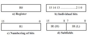
- The registers may be represented(register format) as –
- Register: A register simply can be represented by its name such as R0, R1, R2, etc.
- Individual bits: The individual bits of a register are numbered from 0 (rightmost bit) to n-1 (leftmost bit).
- Numbering bits: The name (R1) of the common register of size 16-bit register can be represented as from 0 to 15 as a whole.
- Subfields: The name of the 16-bit register is IR (Instruction Register) which is partitioned into two subfields i.e. bits 0 through 7 (8 bits) are assigned the symbol IR(L) (for Low order byte) and bits 8 through 15 (8 bits) are assigned the symbol IR(H) (for high order byte).
-
- Information transfer from one register to another is designated in symbolic notation by a replacement operator. For example, the statement R2 ← R1 denotes a transfer of all bits from the source register R1 to the destination register R2 during one clock pulse and the destination register has a parallel load capacity. However, the contents of register R1 remain unchanged after the register transfer micro-operation. More than one transfer can be shown using a comma operator.
- If the transfer of data is to occur only under a predetermined control condition, then this condition can be specified as a control function. For example, if P is a control function then P is a Boolean variable that can have a value of 0 or 1. It is terminated by a colon (:) and placed in front of the actual transfer statement. The operation specified in the statement takes place only when P = 1. The statements can be represented as: –
If (P =1) then (R2 ← R1) or P: R2 ← R1, Where P is a control function that can be either 0 or 1. - All micro-operations written on a single line are to be executed at the same time provided the statements or a group of statements to be implemented together are free of conflict. A conflict occurs if two different contents are being transferred to a single register at the same time or like that. For example, the statement: new line X: R1← R2, R1← R3 represents a conflict because both R2 and R3 are trying to transfer their contents to R1 at the same time.
- A clock is not included/displayed explicitly in any statements. However, it is assumed that all transfers occur during the clock edge transition immediately following the period when the control function is 1. All statements imply a hardware construction for implementing the micro-operation statement as shown below: –
Implementation of controlled data transfer from R2 to R1 only when T = 1
T: R1 ← R2 - In Register to Register Transfer:
- Example: (copy the contents of register R2 into register R1)
- Register to Memory Transfer:
- Example: (store the contents of register R1 into memory address 1000)
- Memory to Register Transfer:
- Example: (load the contents of memory address 1000 into register R1)
- I/O to Register Transfer:
- Example: (read data from an I/O device into register R1)
- Register to I/O Transfer:
- Example: (write data from register R1 to an I/O device)
(2) Arithmetic Micro-Operations :
- This micro-operation performs simple arithmetic operations on numeric data stored in registers.
- The basic arithmetic micro-operations are addition, subtraction, increment, decrement, and shift.
- Addition micro-operation can be represented as:
R3 ← R1 +R2
Here, the contents of register R1 are added to the contents of register R2, and the sum is transferred to register R3. This operation requires three registers to hold data along with the Binary Adder (Binary adder is a digital circuit that generates the arithmetic sum of two binary numbers of any length and is constructed with full-adder circuits connected in cascade. An n-bit binary adder requires n full-adders.) circuit in the ALU.
Add micro-operation, in the accumulator machine, which can be represented as:
AC ← AC + DR
- Subtraction micro-operation is often implemented in machines through complement value and adds operations. It can be represented as:
R3 ← R1 − R2
R3 ← R1 + (2’s complement of R2)
R3 ← R1 + (1’s complement of R2 + 1)
R3 ← R1 + R2 + 1 (The bar on top of R2 implies 1’s complement of R2 which is bitwise complement)
Adding 1 to the 1’s complement produces the 2’s complement. Adding the contents of R1 to the 2’s complement of R2 is equivalent to subtracting the contents of R2 from R1 and storing the result in R3.
- Increment micro-operation: The increment micro-operation adds one to a number in a register. This operation can be represented as:
R1 ← R1 + 1
This can be implemented in hardware by using a binary-up counter. - Decrement micro-operation: The decrement micro-operation subtracts one from a number in a register. This operation can be represented as:
R1 ← R1 – 1
This can be implemented using a binary-down counter. - Multiply & Division micro-operation: In most of the older computers multiply and divisions were implemented using add/subtract and shift micro-operations.
(3) Logic Micro-Operations :
- This micro-operation performs bit manipulation (logic) operations on non-numeric data stored in registers.
- Logic operations are binary operations, which are performed on the string of bits stored in the registers.
- These micro-operations can be used in implementing some of the important applications of manipulation of bits of a word, such as changing some bit values or deleting a group of bits.
- For a logic micro-operation, each bit of a register is treated as a variable.
- A logic micro-operation can be represented as:-
R1 ← R1.R2 specifies AND operation to be performed on the contents of R1 and R2 and stores the results in R1.
- For example, if R1 and R2 are 8 bits registers and suppose R1 contains 10010011 and R2 contains 01010101 then R1 finally will contain 00010001 after AND operation.
- Some of the common logic micro-operations are AND, OR, NOT or Complement, Exclusive OR, NOR, and NAND. In many computers only four: AND, OR, XOR (exclusive OR) and complement micro-operations are implemented.
- Types of Logic Micro-operations
There are the following types of logic micro-operations that need to be performed on different types of data manipulation –
(a) Selective Set
-
- This operation sets those bits in Register R1 for which the corresponding R2 bit is 1.
-
For example: –
(b) Selective Clear
-
- This logic operation clears those bits in register R1 for which corresponding R2 bits are 1.
- For example :
(c) Selective Complement
(d) Mask Operations
(e) Insert
(f) Clear
(4) Shift Micro-Operations :
- This micro-operation performs shift operations on data stored in registers.
- These operations shift the bits of a register left or right.
- There are the following types of shift micro-operations –
- Logical Shift Left (LSL):
- Example: (shift the contents of register R1 one bit to the left, inserting a 0 in the least significant bit)
- Logical Shift Right (LSR):
- Example: (shift the contents of register R1 one bit to the right, inserting a 0 in the most significant bit)
- Arithmetic Shift Left (ASL):
- Example: (similar to logical shift left, but often used in arithmetic operations)
- Arithmetic Shift Right (ASR):
- Example: (similar to logical shift right, but often used in arithmetic operations shift the contents of register R1 one bit to the right, preserving the sign bit)
- Rotate Left (ROL):
- Example: (rotate the bits of register R1 to the left, with the most significant bit moving to the least significant bit)
- Rotate Right (ROR):
- Example: (rotate the bits of register R1 to the right, with the least significant bit moving to the most significant bit)
- Logical Shift Left (LSL):
(5) Control Micro-Operations :
These operations control the sequence of execution of instructions and the flow of data within the CPU.
- Program Counter (PC) Operations:
- Example: (increment the program counter to point to the next instruction)
- Conditional Branching:
- Example: (if the zero flag is set, load the address into the program counter)
- Unconditional Branching:
- Example: (load the address into the program counter, jumping to a new instruction)
- Interrupt Handling:
- Example: and (save the current program counter and load the interrupt vector address into the program counter)
![]()
0 Comments