Introduction of Multiplexer
- A multiplexer is often abbreviated as MUX.
- It is a fundamental building block in digital circuit design.
Definition
- A multiplexer is a digital electronic circuit used in digital systems that performs the function of selecting one of many input signals and forwarding them to a single output line.
Characteristics
- Multiplexers are the fundamental components of digital electronics.
- Multiplexers are versatile and widely used in digital design because they provide a means of selecting and switching between multiple inputs efficiently.
Structure
A typical Multiplexer consists of the following components-
- Input Lines (Data Inputs):
- A multiplexer has multiple input lines, typically labeled as D0, D1, D2, …, Dn, where “n” represents the number of input lines.
- These lines carry the data or signals to be selected.
- Selection or Select Lines (Control Inputs):
- This is one of the most important components of multiplexers.
- Multiplexers may have one or more selection lines (also called control inputs) that determine which input is routed/passed to the output.
- The number of selection lines (n) determines the number of input lines (2n) present in a multiplexer. Thus, Multiplexers may exist in various configurations, which specify the number of input channels/lines they can handle and a single output line. Thus, a standard Multiplexer would be –
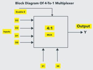
- 2X1 MUX [two data inputs line(D0 & D1), one select line (S), and one data output (Y). ],
- 4X1 MUX
- 8X1 MUX
- 16X1 MUX etc.
- Output Line (Data Output):
- There is always a single output line, labeled as “Y” in a multiplexer that carries the selected input to the output line.
- Enable Line (E):
- This line makes the multiplexer active or non-active.
Representation
A multiplexer can be represented as/in the form of –
- Block Diagram
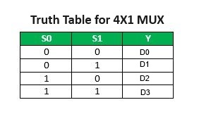
- Truth Table
-
- The truth table representation of multiplexers defines the behavior and specifies the relationship between the selection lines and the selected input.
- The truth table also indicates which input is connected to the output for each combination of selection line values.
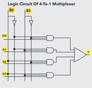
- Logic Circuit Diagram
- In circuit diagrams, multiplexers are represented by specific logic symbols that indicate the number of inputs and select lines.
Use/Applications
- Multiplexers are often used in combination with other digital logic gates and circuits to build more complex systems, such as data multiplexing in communication systems, memory address decoding, and control signal generation in microprocessors. The common uses of Multiplexers are –
- Data Routing: Multiplexers are used to select one of several data sources and route it to a common destination, such as in communication systems and data switchers.
- Control Signal Selection: In digital systems, multiplexers are used to select control signals that determine various operations or modes of operation.
- Memory Addressing: Multiplexers are used in memory address decoding, where they help select a specific memory location for read or write operations.
- ALU (Arithmetic Logic Unit): In microprocessors and CPUs, multiplexers are used in the ALU to select operands and operations based on control signals.
- Data Compression: Multiplexers are used in data compression algorithms to select the appropriate encoding method based on data patterns.
- Analog-to-Digital Conversion (ADC): Multiplexers are used in ADCs to select input channels from multiple analog sources for conversion into digital values.
![]()
0 Comments