Transmission/Communication Medium:
- Transmission channel:
- A communication medium is also roughly known as a Transmission channel.
- Actually, transmission channel and transmission media are closely related but not exactly the same, although they are often used interchangeably in basic networking discussions.
- Transmission media refer to the real physical or wireless medium through which data signals travel from the sender to the receiver, whereas a transmission channel refers to the virtual logical path(within the physical medium at a particular moment) or frequency band(in wireless medium) used to carry data over a transmission medium.
- The transmission medium is the physical path/connection between transmitting and receiving devices in a data transmission system of a computer network.
- Transmission media is one of the major components of a communication system/computer network.
- The characteristics and quality of a data transmission are determined both by the characteristics of the medium and the characteristics of the signal transmitted.
Classification of Transmission Medium
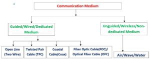
- Transmission media can be broadly classified as guided/wired/dedicated or unguided/wireless/Non-dedicated medium.
[A] Guided Transmission Medium:
- Guided media provide a physical connection between two devices.
- With guided media, the waves/signals are guided as a solid medium/cable.
- These are unidirectional transmissions.
- In the case of guided media, the medium itself is more important in determining the limitations of transmission.
- Examples are twisted pair cable, coaxial cable, and optical fiber.
(a) Twisted Pair Cable(TPC):
Features:
-
- The pair of wires in tpc forms a circuit that can transmit data.
- A twisted pair has a bandwidth-to-distance ratio of about 1 MHz per kilometer.
- The performance of the twisted pair can be substantially improved by adding a metallic shield around the wires.
- Structure:
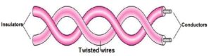
- It consists of two separate wires/conductors, which are normally made of copper and twisted with each other and make a single one.
- Here, each conductor has its own plastic insulation, typically 1 mm thick.
- These cables are twisted together. The wires are twisted in a helical form, similar to a DNA molecule.
- Twisting of the wire is done to reduce crosstalk and noise generated by adjacent pairs during data transmission.
-
-
- Working Mechanism:
- When electrical current flows through a tpc wire, it creates a small, circular magnetic field around the wire, which is nullified by these two wires themselves due to they are placed close together and their magnetic fields are the exact opposite of each other. Thus, the two magnetic fields cancel each other out, and they also cancel out any outside magnetic fields.
- Twisting the wires can enhance this cancellation effect.
-
Types:
-
- Twisted pair cabling comes in several varieties, two of which are very important: Category 3(CAT3) and Category 5(CAT5). Category 5 has more twists per centimeter, resulting in less crosstalk and a better quality signal.
- There are two types of TPC –
(i) Unshielded Twisted Pair[UTP] Cable and (ii) Shielded Twisted Pair[STP] Cable.
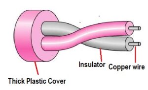
(i) Unshielded Twisted Pair[UTP] Cable:
-
-
- It is an ordinary type of TPC and is used in a variety of networks.
- It is the most common kind of copper telephone wiring.
- Mainly used in the home network.
- Each of the eight individual copper wires (4 pairs) in the UTP cable is covered by an insulating material. In addition, the wires in each pair are twisted around each other.
- UTP cable is created by considering the cancellation effect produced by the twisted wire pairs to limit signal degradation caused by electromagnetic interference (EMI) and radio frequency interference (RFI). To further reduce crosstalk between the pairs in UTP cable, the number of twists in the wire pairs varies per meter/3.28feet.
-
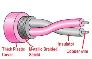
(ii) Shielded Twisted Pair[STP] Cable:
-
-
- It is a specialized type of tpc, i.e., shielded twisted pair is a special kind of copper telephone wiring used in some business installations.
- Shielded wires are much more resistant to thermal noise and crosstalk effects.
- Mainly used in the business network.
- STP is similar to UTP in that the wire pairs are twisted around each other; i.e., STP also has shielding around the cable to further protect it from external interference.
- The extra shielding further reduces the chance of crosstalk, but the shielding increases the overall diameter and weight of the cable.
- The maximum segment length of STP cable is 100 meters.
- An outer covering or shield is added to the ordinary twisted
pair telephone wires; the shield functions as a ground. - Shielded twisted-pair (STP) cable combines the techniques of shielding, cancellation, and wire twisting. Each pair of wires is wrapped in a metallic foil. The four pairs of
wires are then wrapped in an overall metallic braid or foil. - It is usually a 150-ohm cable, as specified for use in Ethernet network installations.
- STP reduces electrical noise both within the cable (pair-to-pair coupling, or crosstalk) and from outside the
cable (EMI and RFI).
-
Advantages:
-
- Twisted pair cable is the most widely used transmission medium for data transmission in a local area network.
- Twisted Pairs are very effective for relatively short distances (a few hundred feet), but can be used for up to a few kilometers.
- It is the least expensive type of local-area network (LAN) cable.
- Most networks today contain some part of twisted-pair cabling at some point along the network.
- It is easier to handle, install, and run.
Disadvantages:
-
- TPC is limited in distance, bandwidth, and data transmission rate.
- It has higher attenuation.
- Low durability cable, and hence must be maintained at regular intervals.
- UTP requires proper grounding at both ends.
- STP cable is heavier and costlier.
Use:
-
- Twisted-pair cable is mainly used for long-distance connections in (old) telephone communication lines and in most modern Ethernet LAN networks.
(b) Coaxial Cable (Coax):
Features:
-
- Structures:
-
- Coaxial cable consists of two conductors, i.e., it consists of a hollow outer cylindrical conductor that surrounds a single inner wire conductor. The inner conductor is held in place by either regularly spaced insulating rings or a solid dielectric material. The outer conductor is covered with a jacket or shield.
- A single coaxial cable has a diameter of from 0.4 to about 1 inch. Because of its shielding, concentric construction, coaxial cable is much less susceptible to interference and cross-talk than is twisted pair.
-
- Coaxial cable is used to transmit both analog and digital signals.
- Structures:
Advantages:
-
- It operates over a wider range of frequencies, i.e,. using frequency-division multiplexing, a coaxial cable can carry over
10,000 voice channels simultaneously. - Coaxial cable can be used over longer distances and supports more stations on a shared line than twisted pair.
- Coaxial cable is perhaps the most versatile transmission medium and has widespread use in a wide variety of applications.
- Using digital signaling, coaxial cable can be used to provide high-speed I/O channels on computer systems.
- It operates over a wider range of frequencies, i.e,. using frequency-division multiplexing, a coaxial cable can carry over
Disadvantages:
-
- They are bulky.
- It is expensive to install for longer distances because of its thickness and stiffness.
- It needs to be grounded to limit interference.
- They are not supported by fast networking standards.
- It is easy to tap the coaxial cable by breaking it and inserting a T-joint in between.
Use:
The most important use of this cable is-
ii) Long-distance telephone transmission with quality.
iii) Short-run computer system links.
iv) In Local Area Networks
(c) Optical Fiber Cable (OFC):
Features:
-
- One of the most significant technological breakthroughs in data transmission systems came into existence when the development of fiber optic cable.
- Various types of glasses and plastics can be used to make different types of optical fibers.
- An optical fiber is a thin (2 to 125 nm(nano meter), flexible medium capable of conducting an optical ray.
- Optical fibers can provide bandwidth-to-distance ratios in the order of 100s of MHz per kilometer.
- Like other cables, hundreds of optical fibers are usually housed/set within one cable.
- It is believed that they will replace twisted pair residential loops in the near future.
- Structure:
- An optical fiber cable has a cylindrical shape and consists of three concentric sections: the core, the cladding, and the jacket.
- In other words, an optical fiber consists of two concentric cylinders: an inner core surrounded by a cladding. Both the core and the cladding are made of transparent plastic or glass material, which transmit signals in the form of light.
- The core is the innermost section and consists of one or more very thin strands, or fibers, made of glass or plastic.
- Each fiber is surrounded by its own cladding, a glass or plastic coating that has optical properties different from those of the core.
- The outermost layer, surrounding one or a bundle of cladded fibers, is the jacket. The jacket is composed of plastic and other materials layered to protect against moisture, abrasion, crushing, and other environmental dangers.
- An optical transmission system has three components: the light source, the transmission medium, and the detector.
- The transmitter generates the light pulses based on the input electrical signal. The transmission medium (usually light) carries the pulse at the speed of light. The detector regenerates the electrical signal based on the light signal it detects on the transmission medium.
- Working Mechanism:
- Optical fibers use the principle of reflection of light to guide light through a channel where the density of the core and cladding must differ sufficiently to reflect the beam of light instead of refracting.
- Here, the core is used for guiding a light beam, whereas the cladding (which has a different refractive index) acts as a reflector to prevent the light signal instead of electrons.
- The signal is usually generated by a laser or Light Emitting Diode (LED).
- In this transmission, a pulse of light indicates a bit 1, and the absence of light indicates a bit 0.
- The transmission medium is an ultra-thin fiber of glass, like a thin needle.
- By attaching a light source to one end of an optical fiber and a detector to the other, we have an unidirectional data transmission system that accepts an electrical signal, converts and transmits it by light pulse, and then reconverts the output to an electrical signal at the receiving end.
- Fiber optics with ultrapure fused silica components shows the lowest rate of data losses, which is difficult to manufacture. But higher-loss multi-component glass fibers are more economical and still provide good performance, which is normally used on a large scale. Plastic-made fiber is even less costly and can be used for short-haul links, for which moderately high losses are acceptable.
- Fiber optic cables are much more secure for data transfer, since it is very difficult to tap fiber optic cables.
- Fiber optic cables are much thinner and lighter than copper cables, so less weight.
Types:
-
- Optical fiber is of two types-
a) Single-mode optical Fiber.
b) Multimode Optical Fiber.
a) Single-Mode Optical Fiber
-
-
- This fiber itself is manufactured with a much smaller diameter than that of multimode fibers, and with substantially lower density (index of refraction).
- This uses step-index fiber and a highly focused source of light that limits beams to a small range of angles, all close to the horizontal.
- The decrease in density results in a critical angle that is close enough to 90 degrees to make the propagation of the beam delays negligible.
- All of the beams arrive at the destination together and can be recombined without distortion to the signal.
-
b) Multimode Optical Fiber
Advantages:
-
- Optical fiber cable is widely used as a backbone for the network due to –
- It has the highest data transmission rate.
- Bandwidth is higher.
- It is lighter in weight.
- It shows low interference.
- It required less number of repeaters in its connection.
- It covers long-distance connections/telecommunications due to low power loss.
- It does not suffer from the various noise problems associated with electromagnetic signals.
- Since there is no electricity used, there is no electrical interference and related noise.
- The optical cable is resistant to electromagnetic interference.
- Higher Bandwidth – it can support higher bandwidth and hence can transfer data at a higher rate.
2) Less signal attenuation – its transmission distance is greater than the twisted pair, and it can run for 50Kms without regeneration.
3) Immunity to electromagnetic interface
4) These cables are much lighter than the copper cables
5) These cables are more immune to tapping than copper cables.
- Optical fiber cable is widely used as a backbone for the network due to –
Disadvantages:
-
- They are fragile and more vulnerable to damage. If we bend fiber optic cables beyond a limit, they will break.
- High manufacturing cost.
- The setup/installation cost is high, i.e., it needs costly splicing/joining tools or machines. The cables and interfaces used are relatively expensive.
- Fiber optic cables are difficult to splice/join.
- Maintenance cost is also high.
- The working mechanism is comparatively complex.
- Installation or maintenance – it needs trained specialists to install fiber optic cables, which are not available everywhere.
- Unidirectional – Propagation of light is unidirectional, and we need two fibers for bidirectional communication.
Use:
-
- Widely used in making fast & sensitive data transmission networks.
- They are being increasingly used as telecommunication carriers for long-distance digital trunk lines.
[B] Unguided Transmission Medium:
- It is often called wireless communication.
- Unguided media transport data/signal mainly through electromagnetic waves/air without using any physical media or a physical conductor.
- Its Signals are broadcast through air (mostly) or water(rarely), and thus are available to anyone who has a device capable of receiving them.
- The electromagnetic spectrum of frequencies ranging from 3 kHz to 900 THz is used for wireless communication.
- With unguided media, the waves/signals are transmitted in all directions (omnidirectional) as air passes.
- The atmosphere and outer space support unguided transmission.
- Examples are – Infra red wave, Microwave, Radio wave, etc.
- Unguided radio signals can travel from the source to the destination in several ways.
- Ground Propagation :
- In ground propagation, radio waves travel through the lowest portion of the atmosphere, hugging the earth.
- These low-frequency signals emanate in all directions from the transmitting antenna and follow the curvature of the Earth.
- The distance depends on the power of the signal.
- Sky Propagation
- In Sky propagation, higher-frequency radio waves radiate upward into the ionosphere, where they are reflected back to earth.
- This type of transmission allows for greater distances with lower power output.
- Line-of-Sight Propagation
- In Line-of-Sight Propagation, very high frequency signals are transmitted in straight lines directly from the source antenna to the destination antenna.
- Antennas must be directional, facing each other, and either tall enough or close enough together not to be affected by the curvature of the earth.
- Ground Propagation :
(a) Infra-red Wave:
Features:
-
- A wave having frequencies from 300 GHz to 400 THz[Tera-Hertz] (wavelengths from 1 mm to 700 nm) is called Infra-red.
- Data transmission rates are similar to twisted pair cables.
- Infrared signals are generated and received using optical transceivers.
- This transmission cannot be affected by another system in the next room.
- They are useless for long-range communication.
- Infrared waves cannot be used outside a building because the sun’s rays contain infrared waves, which can interfere with the communication.
Advantages:
-
- They have high frequencies, which therefore prevents interference
between one system and another. - Infrared systems represent a cheap alternative to most other methods because there is no cabling involved, and the necessary equipment is relatively cheap.
- Infrared, having a wide bandwidth, can be used to transmit digital data with a very high data rate.
- They have high frequencies, which therefore prevents interference
Disadvantages:
-
- Infrared signals can be used for short-range communication.
- They cannot penetrate walls because they are weak signals.
- It cannot be used outside the building as sun rays contain infrared, which leads to interference in communication.
Use:
-
- Infrared signals can be used for communication between keyboards, mice, and printers.
- One recent use of infrared has been for interfacing hand-held and portable computing devices to Local Area Networks.
- The Infrared Data Association (IrDA), an association for sponsoring the use of infrared waves, has established a standard for using these signals for communication between devices such as keyboards, mice, PCs, and printers. Infrared signals defined by the IrDA transmit through line of sight; the IrDA port on the keyboard needs to point to the PC for transmission to occur.
(b) Microwave:
Features:
-
- A wave having frequencies between 1 GHz to 300 GHz is called a microwave.
- Microwaves are unidirectional, i.e., the sending and receiving antennas need to be straight aligned.
- Microwave is by far the most widely used form of radio transmission.
- It operates in the GHz range with data rates in the order of hundreds of Mbps per channel.
- Structure:
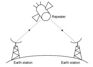
- An important form of microwave system is a satellite system, which is essentially a microwave system plus a large repeater as a satellite in the sky. The signals transmitted by earth stations are received, amplified, and retransmitted to other earth stations by the satellite, which acts as a repeater.
-
- The bandwidth of microwave systems is subdivided into channels of 10s of MHz each, providing data rates in the order of 100s of Mbps. Because of their high bandwidths, satellites are capable of supporting an enormous number and variety of channels, including TV, telephone, and data.
- Microwave transmission occurs in two ways: (i) through a unidirectional antenna and (ii) through an artificial satellite relay.
- (i) Microwave antennas are of two types: the parabolic dish antenna and the horn antenna.
- A parabolic dish antenna is based on the geometry of the parabola. Every line parallel to the line of symmetry reflects off the curve at angles such that all the lines intersect in
a common point called the focus. The parabolic dish works as a funnel, catching a wide range of waves and directing them to a common point. - A horn antenna, on the other hand, looks like a gigantic scoop. Here, outgoing transmissions are broadcast up a stem and deflected outward in a series of narrow parallel beams by the curved head. Received transmissions are collected by the scooped shape of the horn, in a manner similar to the parabolic dish, and are deflected down into the stem.
- A parabolic dish antenna is based on the geometry of the parabola. Every line parallel to the line of symmetry reflects off the curve at angles such that all the lines intersect in
- (ii) Satellite relay –
- It requires a geo-stationary orbit with a height of 35,784km to match the Earth’s rotation.
- It has an uplink that receives transmission on one frequency and a downlink that transmits on a second frequency.
- It operates on several frequency bands known
as transponders. - It can operate in two ways:-
a) Point-to-point- Ground station to satellite to ground station.
b) Multipoint (Broadcast link)- Ground station to satellite to multiple receiving stations.
- Working Mechanism:
- When an antenna transmits microwave waves, they can be
narrowly focused. This means that the sending and receiving antennas need to be aligned. - Here, a pair of antennas can be aligned without interfering with another pair of aligned antennas.
- When an antenna transmits microwave waves, they can be
Advantages:
-
- Microwaves are widely used for point-to-point communications because their small wavelength allows conveniently-sized antennas to direct them in narrow beams, which can be pointed directly at the receiving antenna.
- Higher data rates are transmitted/achieved as the bandwidth increases.
- Low power consumption as the signals are of higher frequencies.
- The unidirectional property of microwave helps in avoiding interference between a pair of aligned antennas.
Disadvantages:
-
- The propagation of microwave is line-of-sight. The problem with this propagation is that towers that are far apart from each other need to be very tall.
- Line-of-sight will be disrupted if any obstacle, such as a new building, is in the way.
- Microwaves suffer from attenuation due to atmospheric conditions.
- Signals are absorbed by the atmosphere.
- For long-distance communication, repeaters are often needed.
- Even high-frequency microwaves cannot penetrate walls.
- Towers are expensive to build.
- High-frequency microwaves cannot be received inside the building.
Use:
-
- Microwave transmission is commonly used in point-to-point communication systems on the surface of the Earth, in satellite communications, and in deep space radio communications.
- They are also used for radars, radio navigation systems, sensor systems, and radio astronomy.
- Microwaves are also used in unicast communication, such as cellular telephones, satellite networks, and wireless LANs.
- Telecommunication carriers and TV stations are the primary users of microwave transmission.
(c) Radio Wave:
Features:
-
- Electromagnetic waves ranging in frequencies between 3 kHz (kilohertz) and 1 GHz(gigahertz) are normally called radio waves.
- They use the reflected and refracted principles of light to change their direction, and hence are ideal for communications.
- It uses an omnidirectional antenna for data transmission that travels in all directions from the source.
- Here, the sending and receiving antennas do not have to be aligned.
- Used in Wi-Fi, Bluetooth, cellular networks, and satellite communication.
- In a wireless network, a device’s transmitter converts digital data (1s and 0s) into a radio signal by modulating a carrier wave. This signal is broadcast through an antenna. A receiver on another device captures this wave and demodulates it, converting it back into the original digital data.
Advantages:
-
- Users can connect to the network while moving around, i.e., allowing devices to communicate without physical cables, forming the basis of wireless computer networks.
- Radio waves are easy to generate and can travel long distances and can penetrate buildings easily; therefore widely used for communication.
- Radio signals have been used for a long time to transmit analog information.
- They are particularly preferred for long-distance communication over difficult terrain or across the oceans.
- Because of the ability to pass through the ionosphere (top) layer of atmosphere, radio waves are suitable for satellite-to-earth transmission.
- Radio waves are suitable for long-distance wireless data transmission.
- Radio waves/signal can be received both inside and outside of the building.
Disadvantages:
-
- Prone to interference from other electronic devices.
- Security concerns due to open and long-distance transmission.
- All devices on a single channel compete for transmission time, which can lead to congestion and lower speeds in crowded areas.
Use:
-
- The short wave form (2400 to 2480 MHz) of Radio waves is mainly used in Bluetooth technology, which is a proprietary wireless technology standard used for exchanging data over short distances in mobile phones and other related devices. It allows wireless devices to be connected to wireless hosts, which may be a computer over short distances. It helps in transferring data between a mobile phone and a computer, provided both have Bluetooth technology.
- Radio waves are used for multicast communications such as radio (AM and FM radio), maritime radio, television, cordless phones, and paging systems.
- Radio waves are very useful in multicasting and are hence used in AM and FM radios, cordless phones, and paging.
- They are used in standard broadcast radio and television, shortwave radio, navigation and air-traffic control, cellular telephony, and even remote-controlled toys.
- Recently, an increasingly popular usable form of radio waves is in cellular radio, which is currently being used by carriers for providing mobile telephone networks. These operate in the VHF (Very High Frequency) band and subdivide their coverage area into conceptual cells, where each cell represents a limited area that is served by a low-power transmitter and receiver station. As the mobile user moves from one cell area to another, its communication is handed over from one station to another.
(d) Satellite Communication:
-
- Satellite communication is a critical component of modern computer networks.
- Satellite communication refers to the use of artificial satellites orbiting the Earth to facilitate the transmission of data, voice, and video signals between distant locations.
- In computer networking, satellite communication is a type of wireless technology that uses artificial satellites orbiting the Earth to transmit and receive data between two or more locations.
- It serves as a critical component of the global Wide Area Network (WAN) infrastructure, enabling data connectivity in places where terrestrial networks are unavailable or impractical or have been destroyed.
- Satellites operate in different orbits depending on their purpose:
- Geostationary Orbit (GEO): Approximately 35,786 km above the Earth’s surface. Satellites in GEO remain fixed relative to a specific point on Earth, making them ideal for continuous communication.
- Medium Earth Orbit (MEO): Between 2,000 km and 35,786 km. Used for navigation systems like GPS.
- Low Earth Orbit (LEO): Below 2,000 km. Provides lower latency and is used for emerging satellite internet services (e.g., Starlink).
- Working Mechanism of Satellite Communication: The process involves three main segments: the ground segment, the space segment, and the user segment.
-
Ground Segment (The Gateway to the Internet):
- This consists of a teleport or Earth station, which is a large facility with massive dish antennas.
- This station is physically connected to the high-speed terrestrial internet backbone (fiber optic networks).
- Its job is to send data to the satellite (the uplink) and receive data from the satellite (the downlink).
-
Space Segment (The Satellite):
- The satellite itself orbits the Earth. It is equipped with transponders.
- A transponder is a complex radio unit that:
- Receives the weak uplink signal from the ground or user.
- Amplifies the signal significantly.
- Changes its frequency to avoid interference between uplink and downlink signals.
- Broadcasts the strong downlink signal back towards Earth.
-
User Segment (The End User’s Equipment):
- This is what a home or business user has. It is typically a VSAT (Very Small Aperture Terminal), which includes:
- A small dish antenna (e.g., 1-2 meters in diameter).
- A block up-converter (BUC) to transmit signals.
- A low-noise block downconverter (LNB) to receive signals.
- A satellite modem that connects to the user’s computer or local network router.
- This is what a home or business user has. It is typically a VSAT (Very Small Aperture Terminal), which includes:
-
- Use of Satellite Communication :
- Global Coverage: Satellites can provide connectivity to remote and rural areas where laying cables is not feasible.
- Primary Internet Access in Mobile Objects: Satellite transmission provides broadband to rural and remote areas, maritime vessels (ships, yachts), and in-flight Wi-Fi for airplanes. Also, provides broadband internet to remote areas through services like Starlink, OneWeb, and HughesNet.
- WAN Backup Link: Businesses use satellite as a failover link. If their primary fiber connection is cut, their network automatically switches to the satellite link to maintain business continuity.
- Disaster Recovery: When natural disasters (earthquakes, hurricanes) destroy terrestrial infrastructure, portable satellite terminals (like BGAN) can be rapidly deployed to provide vital communication for first responders.
- IoT and M2M Communication: Connecting sensors and devices in remote locations for agriculture, oil and gas pipelines, and environmental monitoring where cellular coverage is nonexistent.
- Broadcast and Multicast: Efficiently delivering the same data to many locations at once. For example, a retail chain can use a satellite link to update pricing and inventory data for thousands of stores simultaneously.
- High Bandwidth: Modern satellites can handle large amounts of data, supporting high-speed internet and multimedia applications.
- Broadcasting Capabilities: Ideal for broadcasting TV signals, weather updates, and emergency alerts to a wide audience simultaneously.
- Telecommunications: Facilitates international phone calls, video conferencing, and VoIP services.
- Military and Defense: Secure communication for military operations, surveillance, and reconnaissance.
- Navigation Systems: Supports global positioning systems (GPS) for location tracking and navigation.
- Weather Forecasting: Collects and transmits meteorological data for weather prediction and disaster management.
- Television Broadcasting: Direct-to-home (DTH) satellite TV services like Dish Network and Sky TV.
-
Challenges of Satellite Communication
-
Latency:
- Signals must travel long distances to and from satellites, causing delays (especially in GEO satellites).
- Typical latency ranges from 250 ms to 700 ms.
-
Cost:
- Launching and maintaining satellites is expensive, making satellite communication less cost-effective compared to terrestrial networks.
-
Signal Interference:
- Weather conditions (e.g., rain, storms) can degrade signal quality, especially in higher frequency bands like Ka-band.
-
Limited Bandwidth:
- Although satellites offer high bandwidth, it is shared among many users, which can lead to congestion during peak usage.
-
Energy Consumption:
- Ground stations and satellites require significant power for signal transmission and reception.
-
Connectors(Cables)
- The connectors are tools or interfaces that is used to connect different types of data communication cables(such as twisted pair cable, coaxial cable, fiber optic cable etc.) at one end with the computer or other network devices (such as hub, switch, router, etc.)at the other end in a network environment for data communication.
- Connectors may be used in LAN, MAN, and WAN.
- There are different types of connectors used uniquely to connect different cables.
- In LAN, commonly used connectors are –
(i) RJ-45/TPC Connector:
-
- RJ stands for registered jack.
- RJ45 connectors are the most commonly used standard type of connectors with Ethernet/TPC cables and networks.
- RJ45 connectors consist of eight pins to which the wire strands of a cable interface electrically.
- Standard RJ-45 pin-outs define the arrangement of the individual wires needed when attaching connectors to a cable.
- RJ-45 connectors are of two types: Male RJ-45 and Female RJ-45. Here, Male RJ-45 is connected with the cables where whereas Female RJ-45 is attached to the devices.
(ii) BNC/Coax connector:
-
- The BNC connector (Bayonet Neill–Concelman) is used to connect/disconnect coaxial cable.
- It features two bayonet lugs on the female connector; mating is achieved with only a quarter turn of the coupling nut.
- BNCs are ideally suited for cable termination for miniature-to-subminiature coaxial cable (e.g., RG-58, 59, to RG-179, RG-316).
- It is used with radio, television, and other radio-frequency electronic equipment, test instruments, video signals, and was once a popular computer network connector.
- BNC connectors are made to match the characteristic impedance of cable at either 50 ohms or 75 ohms.
- It is usually applied for frequencies below 3 GHz and voltages below 500 Volts.
(iii) Fiber Optic Cable Connector
-
- In order for information to be transmitted efficiently, the fiber cores must be properly aligned.
- They are usually devices that can be connected and disconnected repeatedly.
- There are many types of fiber optic cable connectors –
1.) ST (Straight Tip) Connectors:
-
-
- It is a slotted bayonet-type connector with a long ferrule, a common connector for multi-mode fibers.
- The ST connector has been the mainstay of optical fiber connectors for many years.
- It can be found in almost every communications room worldwide, but is used mainly in data communications systems.
- The simple-to-use bayonet locking mechanism reduces the risks of accidental disconnection of fiber connections.
-
2.) SC (Standard Connector) Connectors:
-
-
- It is a push/pull type of connector that can also be used with a duplex fiber connection.
- The SC connector comprises a polymer body with a ceramic ferrule barrel assembly, plus a crimp over sleeve and rubber
boot. - These connectors are suitable for 900μm and 2-3mm cables.
- The connector is precision-made to demanding specifications.
- The combination of a ceramic ferrule with precision polymer housing provides consistent long-term mechanical and optical performance.
-
3.) MT (Multi-fiber) Connector:
-
-
- The MT-RJ connector is a development of the now legendary
MT ferrule. - The MT ferrule, in its various designs, has the ability to connect anything from 2 fibers in the MTRJ to 72 fibers in the latest versions of the MPO connector.
- The MT-RJ connector is a development of the now legendary
-
0 Comments