Introduction
- This is the 2nd layer of the hierarchical OSI model.
- This layer lies between the physical layer and the network layer.
- This is considered the Lower layer of the OSI model.
Features
- The Data Link Layer performs its functions mainly in the LAN area.
- The main network device found at the data link layer is Switch & Bridge.
- The Data Link layer, together with the physical layer, provides a data link connection for reliable transfer of data bits in the form of signals(analog or digital) over an imperfect physical connection between two adjacent nodes(source and destination).
- This layer accomplishes the data transfer where the sender breaks the input data packets into data frames, transmits the frames sequentially, and processes the acknowledgment frames sent back by the receiver.
- Like other layers of the OSI model, this layer also creates its own protocol data unit(PDU) called Frames i.e., this layer adds some control bits to the header section of the previous PDU received from the network layer and converts it into different protocol data units. Thus, Frames typically contain addressing information, such as MAC addresses, which identify the source and destination devices on the local network segment. This addressing enables devices to determine whether a received frame is intended for them.
Structure of Data Link Layer
- The data link layer is subdivided into two sub-layers: (a) Logical Link Control (LLC) sub-layer and (b) Medium Access Control (MAC)sub-layer.
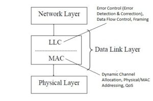
(a) Logical Link Control (LLC) sub-layer
- The LLC is non-architecture-specific and is the same for all IEEE-defined LANs.
- It provides reliable communication between two devices.
- It is also involved with data flow control, error control, framing (encapsulation of network layer data packets into several small pieces of data units called frames), and sequencing.
- LLC protocols are – PPP, HDLC, Frame Relay, ATM, etc.
PPP(Point to Point Protocol)
- Definition
- PPP (Point-to-Point Protocol) is an LLC-type of Data Link Layer (Layer 2) protocol used to establish a direct connection between two network devices for data transmission.
- PPP provides a simple, flexible, and secure method for point-to-point data transmission, making it widely used in WAN and ISP connections.
- Features of PPP
- It is a simple, flexible, and secure method for point-to-point data transmission.
- Functions of PPP
- It supports Point-to-point communication.
- It supports multiple network layer protocols.
- It helps in Framing.
- It establishes and terminates the connection.
- It provides authentication.
- It supports error detection (CRC).
- It encapsulates network layer packets.
- PPP Architecture
- PPP consists of three main components:-
- LCP (Link Control Protocol)
- This protocol establishes, configures, and terminates the link.
- This protocol negotiates the maximum Frame Size (MRU).
- It helps in the authentication method
- Authentication Protocols
- This protocol is used to verify the identity of the communicating devices. This protocol includes –
- PAP (Password Authentication Protocol)
- It has a simple username & password, and the password is sent in plain text. Hence, it is less secure.
- CHAP (Challenge Handshake Authentication Protocol)
- In this protocol, the password is never sent, and hence it is more secure
- NCP (Network Control Protocol)
- This protocol configures network layer protocols
- LCP (Link Control Protocol)
- PPP consists of three main components:-
- Working Mechanism of PPP
- Step1: First, Link Establishment (using LCP).
- Step2: Now, Authentication (Optional).
- Step3: Now, Network Layer Configuration (NCP).
- Step4: Now, Data Transfer.
- Step5: When completed, Link Termination.
- Advantages of PPP
- It supports authentication
- It helps in error detection
- It is multi-protocol support
- It is simple and reliable
- Limitations of PPP
- It does not correct the error.
- It does not provide flow control.
- It supports communication point-to-point only.
- Applications of PPP
- It supports a dial-up Internet connection.
- It supports DSL connections.
- It supports leased line connections.
- It supports VPN tunneling (PPP over Ethernet – PPPoE).
HDLC(High-Level Data Link Control)
- Definition
- HDLC (High-Level Data Link Control) is an LLC-type Data Link Layer protocol, which is a bit-oriented, synchronous Data Link Layer (Layer 2) protocol developed by ISO to provide reliable WAN communication over point-to-point and multipoint links using framing, flow control, and error control.
- Features of HDLC
- It is a bit-oriented protocol.
- It supports synchronous transmission.
- It supports full-duplex & half-duplex modes of communication.
- It provides flow control and error control.
- It supports point-to-point and multipoint communication.
- Functions of HDLC
- It supports framing.
- It supports flow control
- It supports error detection & correction
- It supports reliable data transfer
- It manages the link.
- Types of HDLC Frames
- Information (I-Frame)
- This frame carries user data
- It supports flow & error control
- Supervisory (S-Frame)
- It is used for control information
- It does not carry data
- Unnumbered (U-Frame)
- It is used for link management
- Information (I-Frame)
- HDLC Modes of Operation
- Normal Response Mode (NRM)
- In this, the primary station controls communication, and the secondary responds only when polled.
- Asynchronous Response Mode (ARM)
- In this, the secondary station can transmit without polling.
- Asynchronous Balanced Mode (ABM)
- In this, both stations are equal.
- It is the most commonly used method.
- Normal Response Mode (NRM)
- Advantages of HDLC
- It supports reliable communication
- It has efficient error control techniques.
- It has a flexible frame structure.
- It supports multipoint links.
- Limitations of HDLC
- It has no authentication support.
- It has limited protocol flexibility.
- HDLC has been mostly replaced by PPP in modern networks.
- Applications of HDLC
- It supports leased lines for the Internet.
- It supports WAN communication.
- It supports Router-to-router links.
(b) Medium Access Control (MAC) sub-layer
- The main function of the MAC layer is Dynamic Channel/Medium Allocation (Allocation of a shared single transmission medium by multiple users dynamically).
- It also generates the Physical/MAC Address(=Physical Addressing) of a device.
- It also supports Quality of Service (QoS) regarding transmitting data.
- MAC protocols are – Ethernet (802.3), Wi-Fi (802.11), etc.
Data Link Layers Protocols
- Data Link Layer protocols are broadly classified into:
- Node-to-Node (Data Link Control) Protocols
- These protocols provide reliable communication between two directly connected nodes.
- Examples – Stop-and-Wait Protocol, Stop-and-Wait ARQ, Go-Back-N ARQ, Selective Repeat ARQ, etc.
- Multiple Access Protocols
- These protocols are used when multiple devices share the same communication medium.
- Examples – Aloha, CSMA, Token Passing, etc.
- Node-to-Node (Data Link Control) Protocols
Functions of the Data Link Layer
- The main/primary task of the data link layer is to provide error-free transmission/data delivery on a hop. It accomplishes this task by having the sender configure input data into data frames, transmit the frames sequentially between network devices, and process the acknowledgment frames sent back by the intermediate receiver.
- The data link layer is responsible for reliable node-to-node data transfer over a physical link.
- The data link layer also handles duplexing, which defines how communication occurs between devices. Full-duplex communication allows simultaneous two-way communication, while half-duplex communication allows communication in only one direction at a time.
- It organizes raw bits from the physical layer into frames and ensures error-free and orderly transmission.
- There are the following functions are provided by the data link layer:
- Framing
- Data Delivery
- Flow control
- Error Control(Error detection & correction)
- Physical addressing
- Medium Access Control/Channel Allocation (for shared media)
(I) Framing
- The data link layer takes the variable-length data packets from the network layer above it and divides them into smaller, fixed-length frames. This data segmentation allows for more efficient transmission and error detection.
- Thus, Framing is a crucial process in computer networking and telecommunications, which involves dividing a stream of data packets into several encapsulated, discrete frames, which are smaller units that can be transmitted over a network reliably and efficiently over a communication link.
- In other words, the data link layer groups the data bits (obtained from the physical layer during receiving at the destination) into Frames(= the process is called Framing).
- The framing process adds special bit patterns or control characters at the beginning(header) and end(trailer) of each frame. This creates and recognizes frame boundaries. These delimiters help the receiving device identify the start and end of a frame, ensuring proper synchronization between sender and receiver. Thus, the purpose of framing is to provide a way for the receiver to distinguish individual packets of data and to synchronize its reception with the sender’s transmission.
- Framing often involves adding error-checking information, such as a cyclic redundancy check (CRC) or checksum. These mechanisms allow the receiver to detect and, in some cases, correct errors that might have occurred during transmission.
- Some framing techniques include flow control information, allowing the sender and receiver to regulate the rate of data transmission to avoid overwhelming the receiver.
-
Different networking technologies and protocols use various framing techniques. For example:
-
Ethernet: Ethernet frames are used in wired and wireless local area networks (LANs). They consist of a preamble (used for synchronization and clock recovery), destination and source MAC addresses, a type field (indicating the type of data carried), the actual data, and a checksum.
-
HDLC (High-Level Data Link Control): Used in point-to-point and multipoint links, HDLC frames include address, control, and data fields, along with error-checking mechanisms.
-
PPP (Point-to-Point Protocol): PPP frames are used for establishing connections between network nodes. They include flags for delimiting frames, control fields, address fields, and information fields.
-
Frame Relay: Frame Relay frames contain a DLCI (Data Link Connection Identifier), which helps in routing the frame through the network.
-
-
Several framing methods are commonly used in data link layer protocols, including:
-
Character-Oriented Framing: In this method, frames are delimited by special characters (flags) at the beginning and end. An example of character-oriented framing is the High-Level Data Link Control (HDLC) protocol.
-
Bit-Oriented Framing: A specific pattern of bits is inserted into the data stream to indicate the start and end of a frame. This method helps maintain synchronization between sender and receiver. The Point-to-Point Protocol (PPP) is an example of a protocol that uses bit-oriented framing. Bit stuffing is a technique used in bit-oriented framing. Bit stuffing is a technique used to ensure that a specific sequence of bits (flag pattern) does not occur within the actual data being transmitted. If this sequence appears, an extra bit (0 or 1) is inserted to “stuff” the sequence and maintain frame integrity.
-
Byte-Oriented Framing: In this approach, a count field is added to the beginning of the frame to indicate the number of bytes in the frame. Ethernet frames use a form of byte-oriented framing.
-
(II) Data Delivery
- This layer is responsible for establishing, maintaining, and terminating communication between two directly connected devices, such as two computers or other network devices, called node-to-node or hop-to-hop delivery of data.
- The data link layer is responsible for ensuring reliable communication between two directly connected nodes over a physical link or medium, either wired or wireless. It accomplishes this by managing the framing, addressing, error detection, and flow control of data as it moves between the sender and receiver.
(III) Flow Control
- In network communication, flow control is particularly important when the sender and receiver operate at different speeds or when network congestion can occur. It helps in preventing data loss, buffer overflow, and network congestion, ensuring that data is delivered correctly and at an appropriate pace.
- Flow control in computer networks is a vital mechanism that regulates the rate of data transmission between sender and receiver, preventing data loss, buffer overflow, and network congestion.
- Flow control is a mechanism used in computer networks to manage the flow of data between sender and receiver to prevent data loss or overwhelming the receiving entity.
- Flow control ensures and enhances the efficient and reliable transmission of data across the network by regulating the rate of flow at which data is sent and received.
- Flow control is how to keep the fast sender from overflowing a slow receiver by buffering and acknowledgment procedures.
- Flow control can be implemented at different layers of the network stack, such as the data link layer or the transport layer, depending on the network protocol being used. For example, protocols like TCP (Transmission Control Protocol) use built-in flow control mechanisms to ensure reliable data delivery across IP networks.
- Types of Flow Control:
-
The following types of flow control mechanisms are used in computer networks:
-
Stop-and-Wait Flow Control:
-
-
-
-
-
- This is a node-to-node type of data link layer protocol.
- Stop-and-Wait is a simple and basic flow control protocol in which the sender transmits one frame at a time and waits for an acknowledgment before sending the next frame.
- This method is commonly used in situations where the sender and receiver have significantly different data transmission rates. After sending one frame at a time, the sender waits for an acknowledgment from the receiver before sending the next frame.
- This process ensures that the receiver can handle and process each frame before the next one is sent.
- It is a simple flow control mechanism, and it has low efficiency, or the process rate is slow.
- It does not include any mechanism for error detection or retransmission of lost acknowledgements and frames.
- This protocol focuses only on flow control.
- This protocol assumes an error-free channel.
- It has no retransmission mechanism.
- If a frame is lost or corrupted, communication fails.
- This protocol is used mainly for conceptual understanding.
- Stop-and-Wait controls the flow of data but does not handle transmission errors, whereas Stop-and-Wait ARQ provides both flow control and error control by retransmitting lost or corrupted frames.
-
-
2. Sliding Window Flow Control:
-
-
-
- Sliding window flow control is a more advanced mechanism than stop-and-wait that allows multiple data frames to be in transit simultaneously.
- Sliding Window Flow Control is a data link layer mechanism that allows a sender to transmit multiple frames (window) continuously before receiving acknowledgements, thereby improving bandwidth utilization, transmission efficiency, and throughput.
- In this protocol, the concept of a window is used that defines the range of sequence numbers that can be sent but not yet acknowledged. As acknowledgements arrive, the window slides forward, allowing new frames to be sent. For example –
-
-
-
-
-
- This approach increases the efficiency of data transmission and can adapt to varying network conditions.
- Working Mechanism of Sliding Window
- Step1 : The sender transmits frames within the window limit.
- Step2 : The receiver sends ACKs back for correctly received frames.
- Step3 : Upon receiving ACKs, the sender moves (slides) the window.
- Step4 : New frames are transmitted.
- Advantages
- It has better channel utilization.
- It has a higher throughput.
- It supports high-speed networks.
- Limitations
- It is more complex than Stop-and-Wait.
- It requires buffering and sequence management.
- Types of Sliding Window Flow Control
- There are two types of Sliding Window: (i) Go Back N, (ii) Selective Repeat
-
-
(i) Go-Back-N Flow Control:
-
-
-
-
-
- Go-Back-N Flow Control is a sliding window–based flow control mechanism at the Data Link Layer in which the sender is allowed to transmit multiple(up to N) frames up to a fixed window size while the receiver accepts frames only in order, ensuring controlled data flow without waiting for acknowledgements.
- Go-Back-N flow control improves transmission efficiency by allowing multiple outstanding frames, making it suitable for high-speed communication links.
- Here, the focus of transmission is flow control only, not error control (as in Go-Back-N ARQ).
- The name “Go-Back-N” means that if the receiver cannot accept a frame beyond a certain sequence number, it forces the sender to go back to that point before sending further frames. This ensures receiver synchronization.
- Characteristics
- It uses the sliding window technique.
- It controls the rate of transmission
- Here, the sender window size = N and the receiver window size = 1
- Here, frames are delivered sequentially.
- It prevents receiver buffer overflow.
- Working of Go-Back-N Flow Control
- Step1 : The sender sends multiple frames up to the window size N.
- Step2 : Now, the receiver processes received frames one by one in order.
- Step3 : The receiver sends acknowledgements to regulate the sender.
- Step4 : The sender moves (slides) the window forward as ACKs are received.
- Step5 : The sender pauses transmission when the window is full.
- Advantages
- It has efficient utilization of bandwidth.
- It allows continuous data transmission.
- It has a simple receiver design.
- Limitations
- The receiver cannot accept out-of-order frames.
- It is less flexible compared to the Selective Repeat flow control.
-
-
-
-
(ii) Selective Repeat Flow Control
-
-
-
-
-
- Selective Repeat flow control is a sliding window technique in which the receiver can accept and buffer multiple frames independently, allowing out-of-order reception and efficient data flow.
- Selective Repeat Flow Control is a sliding window–based flow control technique at the Data Link Layer in which the sender can transmit multiple frames, and the receiver can accept, buffer, and acknowledge frames independently, even if they arrive out of order.
- Selective Repeat flow control provides maximum efficiency by allowing both sender and receiver to handle multiple frames simultaneously, making it ideal for high-bandwidth communication systems.
- Characteristics
- It uses a sliding window mechanism.
- Here, the focus is only on flow control, not on error control (as in ARQ).
- Here, the sender window size = N and the receiver window size is also = N.
- Here, frames are individually acknowledged.
- In this, the receiver can store out-of-order frames.
- It ensures smooth data flow without receiver overflow.
- Working Mechanism
- Step1: The sender transmits multiple frames within a window size N.
- Step2: The receiver accepts frames even if they arrive out of order.
- Step3: The receiver buffers out-of-order frames.
- Step4: The receiver sends individual ACKs for each received frame.
- Step5: The sender slides its window forward as ACKs are received.
- Example
-
-
-
-
-
-
-
-
-
- Advantages
- It has high throughput.
- It has better channel utilization.
- The receiver efficiently manages buffer space.
- It is suitable for high-speed networks.
- Limitations
- It is more complex than Go-Back-N.
- It requires a larger receiver buffer.
- Advantages
-
-
-
-
(IV) Error Control
- Data that is either transmitted over a communication channel or stored in memory is not completely error-free.
- In computer networks, error control refers to the techniques and mechanisms used to detect and correct errors that can occur during the transmission of data. These errors can be introduced due to noise, interference, Signal distortion or attenuation, synchronization problems, distorted channels, or other issues in the network.
- The primary goal of error control is to ensure the integrity and reliability of data transmission.
- Error control mechanisms are typically implemented at the data link layer and transport layer of the network stack. Protocols such as Ethernet, Wi-Fi, and TCP/IP incorporate various error control techniques to ensure reliable data transmission across networks.
- Error control mainly includes error detection and error correction.
- Error detection and corrections are two different but related things, i.e., Error detection is the ability to detect errors in transmitting or storing data, and Error correction is the identification and correction of the errors.
- Error detection always precedes error correction.
- Both error detection and correction can be achieved by having extra/redundant/check bits in addition to data, deducing that there is an error.
- There are several methods and protocols used for error control in computer networks.
(a) Error Detection Methods
-
- Error detection techniques are used to identify the presence of errors in the received data.
- Some popular error detection techniques include:-
- Cyclic Redundancy Check (CRC): CRC is a more robust error detection technique that uses polynomial division to generate a checksum. The sender appends the CRC to the data, and the receiver performs the same calculation to check for errors. If the received CRC doesn’t match the calculated one, an error is detected.
- Checksum: A checksum is a simple mathematical algorithm that calculates a value based on the data being transmitted. The receiver performs the same calculation and compares the calculated value with the received checksum. If they don’t match, an error is detected.
- Parity Bit:
- Parity bit check is a simple error detection technique in which an extra bit, called the parity bit, is added to a data unit to make the total number of 1s either even or odd, allowing detection of single-bit errors.
-
Parity check provides a basic level of error detection, suitable for simple and low-cost systems, but is inadequate for modern high-speed networks.
- Types of Parity Check
- Even Parity
- A parity bit is added, so the total number of 1s becomes even.
- For example
- Even Parity
-
-
-
-
- Odd Parity
- A parity bit is added, so the total number of 1s becomes odd.
- For example
- Odd Parity
-
-
-
-
-
-
- Working Mechanisms of Parity Check
-
-
-
-
-
-
- Step1 : The sender counts the number of 1s in the sending data, either odd or even.
- Step2 : Now, adds required parity bit (even or odd).
- Step3 : Finally, the receiver recounts the number of 1s.
- Step4 : If the parity condition fails or is not matched = error is detected.
- Types of Parity Check
- Single Parity Check: One parity bit is used (even or odd) for the entire data unit to detect a single-bit error.
- Two-Dimensional Parity Check: Here, a parity bit is added to rows and columns to detect single-bit errors and some burst errors.
- Applications
- The parity bit mechanism is used in simple communication systems.
- It is also used in memory error detection.
-
-
-
(b) Error Correction Methods
-
-
Automatic Repeat Request (ARQ): It is a mechanism that automatically retransmits lost data when errors are detected. There are several variations of ARQ, including:
-
Stop-and-Wait ARQ:
-
Stop-and-Wait controls the flow of data but does not handle transmission errors, whereas Stop-and-Wait ARQ provides both flow control and error control by retransmitting lost or corrupted frames.
-
Stop-and-Wait ARQ improves the Stop-and-Wait protocol by adding an error control mechanism using acknowledgments, timeouts, and sequence numbers. If a frame or acknowledgment is lost, the sender retransmits the frame, making communication reliable.
-
Stop-and-Wait ARQ is an enhanced version of Stop-and-Wait that provides transmission error control in addition to flow control. If an acknowledgment is not received by the sender within a specified time, the sender assumes an error and retransmits the frame.
-
This method is used in practical/real/common data communication.
-
-
Go-Back-N ARQ: With go-back-n ARQ, the sender can transmit multiple frames without waiting for individual acknowledgments. The receiver acknowledges the correctly received frames, but if an error is detected, it discards the frame and requests the sender to retransmit all subsequent frames.
-
Selective Repeat ARQ: Selective repeat ARQ also allows the sender to transmit multiple frames without waiting for acknowledgments. The receiver acknowledges each correctly received frame individually. If an error is detected, only the damaged frame is retransmitted, while the remaining frames are kept in a buffer at the sender until they are acknowledged.
-
-
(c) Error Detection & Correction Methods
-
-
Forward Error Correction (FEC): FEC is a technique where additional redundant bits are added to the transmitted data to allow the receiver to detect and correct errors without the need for retransmission. FEC codes, such as Reed-Solomon codes or convolutional codes, are widely used for error correction. The receiver uses these redundant bits to reconstruct the original data even if some errors are present.
-
(V) Physical Addressing
- Physical addressing refers to the use of MAC/Physical/Hardware addresses to uniquely identify devices/nodes in a local network at the Data Link Layer (Layer 2) of the OSI model.
-
Physical addressing is used only in local networks, not across the Internet, such as Ethernet (IEEE 802.3), Wi-Fi (IEEE 802.11), Bluetooth, Local Area Networks (LANs), etc.
- Physical addressing enables accurate frame delivery within a LAN using MAC/physical addresses, forming the foundation of local network communication.
-
Functions of Physical Addressing
-
It identifies source and destination devices in a LAN.
-
It ensures the correct delivery of frames.
-
It enables device-to-device communication.
-
It supports switch-based forwarding.
-
- Physical/MAC/Hardware Address
- Physical address is a unique identifier assigned to a network interface card (NIC) by the manufacturer and is generally not modified or changed.
- This address is commonly called a MAC/Hardware address (Media Access Control address).
- The MAC Address Format is of length 48 bits (6 bytes) and is represented in Hexadecimal form now. For Example: 00:1A:2B:3C:4D:5E.
- Structure of MAC Address
- Part – Size – Description
- OUI (Organizationally Unique Identifier) – 24 bits – Identifies manufacturer.
- NIC Identifier – 24 bits – Unique device number.
(VI) Channel Allocation/Medium Access
- This is done by the MAC sub-layer of the data link layer of the OSI model using MAC techniques.
- There are different methods used as access protocols in LANs, in which major techniques are token passing and CSMA/CD. Token passing can be used with ring or bus topologies. CSMA/CD (carrier sense multiple access, with collision detection) is used with the bus and some star topologies.
- The MAC (Medium Access Control) techniques can be broadly divided into four categories: Random Access/Contention-based, Round-Robin-based, Reservation-based, and Channelization-based.
(a) Random Access/Contention Technique Channel Allocation
-
- This channel allocation follows contention-based approaches, hence sometimes called contention techniques.
- Contention techniques are suitable for the bursty nature of traffic.
- In contention techniques, there is no centralized control.
- In this method, when a node has data to send, it contends for gaining control of the medium immediately.
- The principal advantage of contention techniques is their simplicity. They can be easily implemented in each node. The techniques work efficiently under light to moderate loads.
- The performance of this process rapidly falls under a heavy load.
- Types of Random Access :
- The random access allocation method is further categorized into –
(I) Aloha (II) CSMA (III) CSMA/CD (IV) CSMA/CA
(I) Aloha
-
-
-
-
-
Aloha-based channel allocation schemes have been used in early wireless networks and serve as the foundation for more advanced protocols. For instance, Carrier Sense Multiple Access with Collision Detection (CSMA/CD) and Carrier Sense Multiple Access with Collision Avoidance (CSMA/CA) are variants of the Aloha protocol that incorporate additional mechanisms to reduce collisions and improve efficiency in channel access.
- The Aloha protocol was originally developed for radio networks and later adapted for use in various wireless technologies.
-
Aloha and its further advanced variants(such as CSMA, CSMA/CD, CSMA/CA, etc.)provide a way to allocate the shared channel fairly among multiple devices without requiring explicit coordination or centralized control.
-
Aloha refers to a random access protocol used in wireless communication systems to control access to a shared communication channel.
-
The basic idea behind the Aloha protocol is that devices wishing to transmit data over the shared channel do so whenever they have data to send, without first checking if the channel is busy. If two or more devices transmit at the same time and their signals collide, a collision occurs. When a collision happens, the transmitting devices back off for a random period of time and then attempt to retransmit their data.
- Aloha is further divided into two types: (i) Pure Aloha and (ii) Slotted Aloha
-
-
-
-
(i) Pure Aloha:
-
-
-
-
-
- Pure Aloha is an early version of the Aloha protocol used for channel allocation in wireless communication networks.
- It was developed at the University of Hawaii in the early 1970s and was primarily used for satellite communication systems.
- Pure ALOHA is a random access protocol used in computer networks to manage communication between multiple devices sharing a common transmission medium, such as a radio frequency or a coaxial cable.
- In Pure Aloha, devices are allowed to transmit data on the shared channel whenever they have data to send, without checking if the channel is currently being used by other devices. If multiple devices transmit at the same time, collisions occur, and the transmitted data becomes garbled. However, this lack of coordination can lead to collisions when two or more devices transmit simultaneously, resulting in a loss of data. To deal with collisions, Pure ALOHA devices use a technique called “collision detection.”
- When a collision happens, all devices that detect the collision will wait for a random amount of time and then attempt to retransmit their data. This randomization helps to minimize the chances of another collision occurring. However, collisions can still occur if devices randomly choose the same retransmission time.
- In Pure ALOHA, devices are allowed to transmit data whenever they have it, without checking if the medium is busy or if other devices are transmitting.
- When a collision occurs in Pure Aloha, the transmitting devices detect the collision by monitoring the channel for interference. Upon detecting a collision, the transmitting devices wait for a random amount of time and then retransmit their data. The random wait time helps to reduce the probability of collisions recurring.
- Pure Aloha suffers from inefficiency due to the lack of coordination and the possibility of collisions.
- Limitations: Pure ALOHA is a simple protocol but suffers from low efficiency, i.e., the maximum throughput of Pure Aloha is relatively low, at around 18% of the channel capacity under ideal conditions, assuming an infinite number of devices. This low efficiency is due to the high collision rates, especially as the number of devices and traffic load increases and subsequent retransmissions that result from uncoordinated access to the channel.
- Despite its limitations, Pure Aloha laid the groundwork for subsequent improved versions of the Aloha protocol, such as Slotted Aloha and the Carrier Sense Multiple Access (CSMA) variants, which further reduced collisions and improved overall channel efficiency.
- Due to its limitations, Pure ALOHA is not widely used in modern computer networks. It served as the basis for the development of more efficient protocols such as Slotted ALOHA and Carrier Sense Multiple Access (CSMA), which are used in Ethernet networks and other communication systems.
-
-
-
-
(ii) Slotted Aloha:
-
-
-
-
-
- Slotted ALOHA is an improved version of the Pure ALOHA protocol, designed to reduce collisions and improve efficiency in random access networks.
- It was developed as a modification of Pure ALOHA at the University of Hawaii in the early 1970s.
- In Slotted ALOHA, the time is divided into equal-sized discrete slots, and each device is only allowed to transmit data at the beginning of a slot, or devices are synchronized to these time slots. The transmission of data is allowed only at the beginning of each time slot. This synchronization helps to minimize collisions since devices are no longer allowed to start transmission randomly throughout the time frame.
- When a device has data to transmit, it waits for the beginning of the next time slot and transmits its packet. If the transmission is successful without any collision, the receiver acknowledges the successful reception.
- If a collision occurs, the devices involved in the collision do not receive any acknowledgment and wait for a random time interval before attempting retransmission in the next available slot, and then finally retransmit their packets in subsequent time slots. Randomization helps to reduce the chances of collisions happening again.
- The concept of time slots and synchronized transmissions is fundamental to many modern network protocols and systems.
- Slotted ALOHA improves efficiency compared to Pure ALOHA because it reduces the chances of collisions. The maximum system capacity is approximately doubled, reaching around 36% under ideal conditions. This improvement is achieved by the synchronized time slots that ensure devices have an equal opportunity to transmit and reduce the probability of collisions.
- Slotted ALOHA has been used as a basis for the development of other multiple access protocols in network communication, such as CSMA/CD (Carrier Sense Multiple Access with Collision Detection), which is widely used in Ethernet networks.
-
-
-
-
(II) CSMA
-
-
-
-
- CSMA, which stands for Carrier Sense Multiple Access, is a widely used protocol used in computer networks to coordinate access to a shared common communication medium, such as Ethernet networks, and forms the basis for efficient and fair sharing of network resources among multiple devices.
- CSMA protocols aim to avoid or minimize collisions by having devices sense the medium before transmitting. In addition to sensing the medium, devices also monitor for collisions. If a collision is detected during transmission, devices immediately stop transmitting, send a jam signal, and wait for a random backoff period before retransmitting.
- The goal of CSMA is to minimize collisions between devices and ensure efficient and fair sharing of network resources.
- In CSMA, devices that want to transmit data first listen to the medium of the network to check if the medium is idle, i.e., no other device is transmitting. This is known as Carrier Sensing. If the medium is busy, the device waits for a random amount of time and becomes idle before transmitting. This helps to avoid collisions that would occur if multiple devices were to transmit simultaneously. However, even with carrier sensing, collisions can still occur due to the propagation delay of signals across the network.
- CSMA protocols provide a more efficient and collision-free approach compared to random access protocols like Pure ALOHA and Slotted ALOHA.
- They are widely used in various network technologies to optimize communication and ensure efficient utilization of the shared medium
-
-
-
(III) CSMA/CD
-
-
-
-
- CSMA/CD stands for Carrier Sense Multiple Access with Collision Detection.
- CSMA/CD is a media access control (MAC) protocol used in shared Ethernet networks to control access to the shared communication medium, typically a coaxial cable or twisted-pair cable that uses the older 10BASE-T or 100BASE-TX standards.
- In CSMA/CD, each device on the network listens to the transmission medium before sending data. If the medium is idle, the device can transmit its data. However, if multiple devices attempt to transmit at the same time, a collision may occur.
- To detect collisions, devices continue to monitor the channel while transmitting data. If a collision is detected, devices stop transmitting immediately and send a jam signal to ensure all other devices on the network are aware of the collision. After a collision, the devices that were involved wait for a random amount of time before attempting to retransmit the data.
- When a collision is detected, the colliding devices stop transmitting and wait for a random amount of time before attempting to retransmit. This random backoff helps to avoid future collisions. The delay period is longer for each subsequent collision, reducing the probability of repeated collisions.
- To reduce the chances of collisions, CSMA uses a mechanism called Collision Detection. While transmitting, devices continue to listen to the medium to detect if another device is also transmitting simultaneously. If a collision is detected, devices stop transmitting and wait for a random period of time before attempting retransmission.
- CSMA protocols have evolved to include additional features to enhance efficiency, such as CSMA/CD (Carrier Sense Multiple Access with Collision Detection), which is used in Ethernet networks. CSMA/CD improves collision detection by quickly detecting collisions and initiating recovery procedures.
- Working Mechanism of CSMA/CD:-
-
Carrier Sense (CS): Before transmitting data, a device using CSMA/CD listens to the network to check if another device is currently transmitting. If the medium is idle, the device can proceed to the next step. If it detects a signal, it assumes the network is busy and waits for the transmission to complete.
-
Multiple Access (MA): Once the device determines that the network is idle, it can start sending its data.
-
Collision Detection (CD): While a device is transmitting data, it continues to listen to the network. If it detects a collision, which occurs when two or more devices transmit data simultaneously and their signals interfere with each other, it stops transmitting and sends a jam signal to inform other devices about the collision.
-
Backoff and Retransmission: After a collision is detected, each device that was involved waits for a random amount of time before attempting to retransmit its data. This random backoff helps to reduce the likelihood of repeated collisions. The devices follow an exponential backoff algorithm to increase the waiting time if subsequent collisions occur.
-
- CSMA/CD is less/not commonly used today than modern Ethernet networks because modern Ethernet networks are based on fiber optic cables, such as the Gigabit Ethernet or 10 Gigabit Ethernet, which often employ full-duplex communication, where collisions are not possible or where collisions are avoided by using separate transmission and reception channels.
- CSMA/CD was widely used in early Ethernet networks but has been largely replaced by CSMA/CA (Carrier Sense Multiple Access with Collision Avoidance) in modern networks, such as Wi-Fi, which uses a different mechanism to avoid collisions.
-
-
-
(IV) CSMA/CA
-
-
-
-
- CSMA/CA stands for Carrier Sense Multiple Access with Collision Avoidance.
- CSMA/CA is another variant of CSMA, CSMA/CA.
- CSMA/CA is a protocol used in wireless networks, particularly in the IEEE 802.11 family of standards (Wi-Fi), to control access to the shared wireless medium.
- In CSMA/CA, devices contend for the channel by sensing if it is busy or idle before transmitting data. If the channel is idle, the device waits for a random period of time known as a backoff period before transmitting. The purpose of the backoff period is to reduce the likelihood of collisions that could occur if multiple devices start transmitting simultaneously after sensing the channel as idle.
- CSMA/CA introduces a mechanism to avoid collisions by using techniques like request-to-send (RTS) and clear-to-send (CTS) packets, as well as virtual carrier sensing.
- CSMA/CA also implements a technique called Clear Channel Assessment (CCA) to avoid collisions. Before transmitting, a device listens for ongoing transmissions or other sources of interference on the channel. If the channel is busy, the device defers its transmission until the channel becomes idle.
- Furthermore, CSMA/CA employs an acknowledgment mechanism. After transmitting a data frame, the sender waits for an acknowledgment (ACK) from the receiver. If an ACK is not received within a specified timeout period, the sender assumes a collision occurred and initiates a retransmission.
- CSMA/CA is designed to improve the reliability and efficiency of wireless network transmissions by avoiding collisions as much as possible. It is used in various Wi-Fi standards, including 802.11b, 802.11g, 802.11n, and 802.11ac.
- In CSMA/CA, collisions are harder to detect due to the nature of the wireless medium.
- CSMA/CA employs a mechanism called “Request to Send/Clear to Send” (RTS/CTS) to reserve the medium before transmitting. Devices send a request to send a packet and wait for acknowledgment from the receiving device before transmitting. This process helps to avoid collisions by reserving the medium for the intended communication.
-
-
-
(b) Round Robin Channel Allocation
-
- Round-Robin techniques work efficiently when the majority of the stations have data to send most of the time.
- This channel allocation is less effective when only a few nodes have data to send for brief periods of time.
- In Round Robin techniques, each and every node is given the chance to send or transmit by rotation after some time quantum value. When a node gets its turn to send, it may either decline to send or it may send if it has data to send. After getting the opportunity to send, it must relinquish its turn after a maximum period of time. The right to send then passes to the next node based on a predetermined logical sequence. The right to send may be controlled in a centralized or distributed manner. Polling is an example of centralized control, and token passing is an example of distributed control.
- Types of Round-Robin :
- The round-Robin technique is of two types: (i) Polling, (ii) Token Passing
(i) Polling
-
-
-
- Polling is an example of centralized control.
- The working mechanism of polling is similar to the roll-call principle performed in a
classroom. Just like the teacher, a central controller sends a message to each node in turn. The message contains the address of the node being selected for granting access. Although all nodes receive the message, only the addressed node responds, and then it sends data, if any. If there is no data, usually a “poll reject” message is sent back. In this way, each node is interrogated in a round-robin fashion, one after the other, for granting access to the medium. The first node is again polled when the controller finishes with the remaining codes. - The polling scheme has the flexibility of either giving equal access to all the nodes or giving some nodes may be given higher priority than others. In other words, the priority of access can be easily implemented.
-
-
(ii) Token Passing
-
-
-
- Token passing is an example of distributed control.
-
-
For more details, click on this link
(c) Reservation Channel Allocation
-
- Types of Reservation :
- Reservation technique is of two types: (i) Centralised, (ii) Distributed
- Types of Reservation :
(i) Centralized Reservation Channel Allocation
-
-
- Centralized channel allocation, also known as centralized medium access control (MAC), is a network communication method where a central authority or control entity manages and assigns communication channels to network devices.
- In other words, Centralized channel allocation refers to a method of managing the allocation of communication channels in a network from a central authority or controller. In this approach, a central entity, or central controller, network administrator, or base station is responsible for assigning and controlling the use of channels by different devices or users in the network. Thus, centralized channel allocation is a method used to manage and optimize the allocation of communication channels in a network, providing centralized control and efficient utilization of resources.
- The central authority maintains a database or table that keeps track of the available channels and their allocation status. When a device or user wants to establish communication, it requests permission from the central controller to use a specific channel.
- This approach is typically used in centralized network architectures where a central node or controller exists and regulates the channel access for all connected devices.
- In a centralized channel allocation scheme, the central authority determines which devices can transmit data and when they can do so.
- It maintains a schedule or a set of rules for channel access, allowing devices to take turns in using the communication medium. The central entity allocates specific time slots or frequencies to individual devices, ensuring that only one device can transmit at a time.
- The central authority evaluates the channel requests by using various algorithms or protocols, or predetermined criteria to allocate channels efficiently, based on several factors such as device priorities, quality of service requirements, the availability of channels, the priority of the requester, or fairness considerations. It then grants or denies the channel allocation based on these factors.
- Centralized channel allocation can provide better control and coordination in network environments with a central authority.
- It can also dynamically adjust the channel allocation based on network conditions or device demands.
- Advantages: The advantages of centralized channel allocation include efficient channel utilization, centralized control and coordination, and the ability to optimize channel assignments based on network conditions or user requirements. It can also help prevent channel conflicts and interference, improve network performance, and enable effective management of resources in large-scale networks.
- Examples: One example of centralized channel allocation is the Time Division Multiple Access (TDMA) scheme, commonly used in cellular networks. In TDMA, the central authority divides the available time slots into fixed intervals and assigns each device a specific time slot for transmission. This ensures that devices do not interfere with each other and allows efficient sharing of the available bandwidth.
- Limitations: It may also introduce a single point of failure or bottleneck if the central entity malfunctions or becomes overloaded(the network heavily relies on the central controller). Additionally, the centralized approach may not be suitable for networks with high device mobility, or it may require more complex protocols and infrastructure(scalability requirements) to facilitate communication between the central controller and the network devices, as frequent channel allocation updates might be needed.
-
(ii) Distributed Reservation Channel Allocation
-
-
- Distributed channel allocation is a method/technique used in wireless communication systems to allocate available communication channels among multiple users or devices.
- These techniques help optimize channel utilization, improve system capacity, and enhance overall network performance.
- It aims to efficiently utilize the available frequency spectrum while minimizing interference and maximizing system capacity. In other words, it aims to optimize channel utilization and minimize interference by distributing the channel allocation process across the network.
- Instead of having a central authority or base station control the entire channel allocation, distributed channel allocation allows individual devices or nodes in the network to make independent decisions regarding channel selection. This decentralized approach reduces the need for constant coordination and improves the overall efficiency of the network.
- In a distributed channel allocation scheme, the channel allocation decisions are made locally by individual users or devices rather than being centrally controlled by a single entity, where each device typically performs a local assessment of the available channels based on some factors such as signal strength, interference levels, and available bandwidth. Users or devices then autonomously/independently select a channel from the available set of channels that is least congested or interfered with, typically using algorithms like carrier sense multiple access (CSMA) or contention-based protocols. By allowing devices to dynamically adapt their channel allocation based on real-time conditions, distributed channel allocation enables better utilization of available spectrum resources and enhances the overall performance of wireless networks. It also provides flexibility in accommodating changes in network topology and user demands.
- There are various distributed channel allocation algorithms that can be employed, depending on the specific requirements of the system. The choice of the distributed channel allocation algorithm depends on factors such as network topology, traffic patterns, system capacity, interference characteristics, and the level of coordination among users or devices. Some commonly used algorithms are:-
-
-
-
-
-
Random Channel Allocation: In this scheme, users or devices randomly select an available channel from the set of channels. This method is simple but may lead to inefficient channel utilization and increased interference.
-
Distributed Dynamic Channel Allocation: This algorithm allows users or devices to adaptively change their channel allocation based on the current network conditions. It employs techniques such as channel sensing, interference estimation, and channel switching to dynamically adjust the channel assignments.
-
Game Theory-Based Channel Allocation: Game theory can be used to model the interaction between multiple users or devices competing for limited channel resources. Users or devices aim to maximize their own utility while considering the actions of other participants. Game theory algorithms help determine an equilibrium channel allocation strategy that balances the overall system performance.
-
Carrier Sensing Multiple Access (CSMA) and variants: CSMA-based protocols, such as CSMA/CA (Carrier Sense Multiple Access/Collision Avoidance) or CSMA/CD (Carrier Sense Multiple Access/Collision Detection), are commonly used in wireless networks. These protocols involve users or devices sensing the medium for ongoing transmissions and deferring their channel access if they detect activity. They provide a distributed and collision-free channel access mechanism.
-
-
-
-
-
- Distributed channel allocation techniques are used in various wireless communication systems, including cellular networks, Wi-Fi networks, ad hoc networks, and sensor networks.
-
(d) Channelization Channel Allocation
-
- Channelization channel allocation refers to the process of dividing the available frequency spectrum into smaller frequency channels or bands and allocating them to different communication systems or users.
- Channelization and channel allocation are two related concepts in wireless communication systems.
- Channelization refers to the process of dividing the available frequency spectrum into smaller frequency bands or channels. These channels are used to carry individual communication signals, allowing multiple users or devices to transmit and receive data simultaneously without interfering with each other.
- Channel allocation, on the other hand, is the process of assigning specific channels to different users or devices in a wireless network. It determines which channel is allocated to each user for communication.
- In practical terms, channelization is typically performed at the design stage of a wireless system, where the available frequency spectrum is divided into smaller bands or channels based on various factors such as bandwidth requirements, interference considerations, regulatory requirements, and the specific technology being used (e.g., Wi-Fi, cellular).
- Once the channelization is defined, the channel allocation process takes place during the operation of the wireless system. Channel allocation can be done in a centralized or distributed manner.
- In centralized channel allocation, a central authority or base station controls and assigns channels to users or devices based on predetermined rules or algorithms. This approach provides a higher level of coordination and can optimize channel utilization across the network.
- In distributed channel allocation, individual devices or nodes make independent decisions regarding channel selection and allocation. This decentralized approach allows devices to autonomously select channels based on local assessments of channel conditions, such as signal quality, interference levels, and available bandwidth.
- Both channelization and channel allocation are important considerations in wireless communication systems to ensure efficient and reliable transmission of data. Effective channelization helps divide the frequency spectrum to avoid interference, while appropriate channel allocation strategies optimize spectrum usage and enhance network performance.
- It is commonly used in various wireless communication technologies, such as cellular networks, Wi-Fi, and satellite systems.
- Working Mechanism:
The channelization process involves several steps:
-
-
-
-
Frequency Spectrum Analysis: The frequency spectrum is analyzed to determine the available frequency range that can be used for communication. This analysis considers factors such as regulatory restrictions, interference sources, and desired bandwidth.
-
Channel Bandwidth Determination: The bandwidth required for each communication system or user is determined based on their specific requirements. Different technologies may have different channel bandwidths, such as 20 MHz for Wi-Fi or 1.4 MHz for GSM cellular networks.
-
Channel Division: The available frequency spectrum is divided into smaller frequency channels or bands. The division can be done in various ways, such as using frequency-division multiplexing (FDM), time-division multiplexing (TDM), or code-division multiple access (CDMA) techniques.
-
Channel Allocation: The divided channels are allocated to different communication systems or users based on specific allocation policies or algorithms. The allocation process considers factors like available bandwidth, interference levels, quality of service requirements, and system capacity.
-
-
-
- The goal of channelization channel allocation is to efficiently utilize the available frequency spectrum by dividing it into smaller channels and allocating them to different users or systems. This helps to minimize interference, maximize capacity, and optimize the overall performance of wireless communication systems. Effective channel allocation strategies play a crucial role in ensuring reliable and efficient wireless communication in various applications.
![]()
0 Comments