History

  • The concept of Multiplexing originated in telegraphy in the 1870s, and is now widely applied in different streams of communications.

Introduction

  • The transmission of data over a network, either in wireless or wired medium, requires to solve the problem of being able to send a large amount of data among different groups of recipients at the same time without the data/message being mixed up with those of the others. For example, The thousands of radio or television channels that are being broadcast throughout the world simultaneously, or of the millions of telephone conversations that are taking place every minute of the day. This is achieved by a technology called multiplexing.
  • There are some differences in the characteristics of voice and data communication. When one wants to transmit data over a telephone line, we have to make some changes to be able to get sufficiently high speeds. For this, ADSL, a scheme for doing this at rates that can compete on cost and quality with those offered by cable television service providers. 
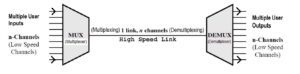
  • Normally, a medium can carry only one signal at any moment in time during data transmission. For multiple signals to share one medium, the medium must somehow be divided, giving each signal a portion of the total bandwidth. This is performed by Multiplexing technique.  
  • The basic aim of the Multiplexing is to share an expensive resource by putting-up multiple signals on the same channel. For example, in telecommunications, several telephone calls may be carried using one wire.

Definition

  • Multiplexing is a technique that allows simultaneous communication at a time by multiple users on the same (single) link.
  • Multiplexing is the process by which multiple signals (that carrying voice calls, data requests etc.) are transmitted over a single shared physical medium (cable or air). 
  • In another words, Multiplexing is a method by which multiple analog message signals or digital data streams are combined into one signal over a shared medium. Thus, Multiplexing refers to the ability to transmit data coming from several pairs of equipment (transmitters and receivers) called low-speed channels on a single physical medium (called the high-speed channel). 

Characteristics

  • The process of multiplexing is done by a device called Multiplexer(MUX) that combines the signals from the different transmitters and sends them over the high-speed channel of a link.
  • A Demultiplexer(DEMUX) is the device which separates signal received from a high-speed channel of a link into different low speed channel of different link and sends them to receivers individually.
  • Multiplexer allow the process of transmitting different type of data such as audio, video at the same time using a single transmission line.

Advantages

  • It makes modern communications possible and so fast.
  • It allows several slower channels or connections, to be collected and aggregated to a faster channel or connection that has a higher bandwidth.
  • It lowers both the cost and the time needed for the deployment of the physical data transmission medium, as a single medium that can serve multiple signals transmission simultaneously.
  • It boosts/improves the technical efficiency of the transmission medium.
  • It increases the utilization of transmission medium/network resources.
  • It makes a communication system powerful.

Disadvantages

  • Extra I/O ports required to control the process of multiplexing.
  • Creates delays in switching ports during transmission.

Applications

  • The use of multiplexer reduces the number of copper lines required to connect the memory circuit to other parts of the computer circuit.
  • Multiplexer can be used for the transmission of data signals from the computer system to a satellite or spacecraft of the ground system using the GPS (Global Positioning System) satellites.
  • In telephone network, multiple audio signals of different users are integrated on a single line for transmission with the help of multiplexers.

Types

  • There are five types of multiplexing involved in data communication –
    1. Frequency division multiplexing (FDM)
    2. Wavelength division Multiplexing (WDM)
    3. Time division Multiplexing (TDM)
    4. Code division Multiplexing (CDM)
    5. Space-division Multiplexing (SDM)

(A) Frequency Division Multiplexing (FDM)

  • This is one of the common method of multiplexing.
  • Here, Bandwidth is divided into different smaller frequency bands (range).
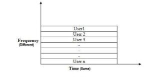
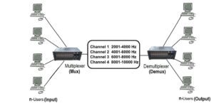
  • In this technique, the available/total bandwidth is divided into a number of smaller independent logical channels with each channel having a small bandwidth and each one of them working with a specific bandwidth. The method of using a number of carrier frequencies each of which is modulated by an independent speech signal is in fact frequency division multiplexing. 
  • This technique is applied in the telecommunication dept./process in which the total bandwidth available in a communication medium is divided into a series of non-overlapping frequencies sub-bands. Each one of these sub-bands then carries a separate signal.
  • This allows a single transmission medium such as a cable or optical fiber to be shared by many signals.

  • An example of a system using FDM is cable television, in which many television channels are carried simultaneously on a single cable. FDM is also used by telephone systems to transmit multiple telephone calls through high capacity trunk lines, communications satellites to transmit multiple channels of data on uplink and downlink radio beams, and broadband DSL modems to transmit large amounts of computer data through twisted pairs telephone lines, among many other uses.
  • Frequency-division multiplexing works best with low-speed devices.
  • The frequency division multiplexing schemes used around the world are very standardized. A wide spread standard is 12, 4000-Hz each voice channels (3000Hz for user, plus two guard bands of 500Hz each) multiplexed into the 60 to 108 KHz band. Many carriers offer a 48 to 56 kbps leased line service to customers, based on the group. 
  • In Telephony, the most widely used method of modulation in FDM is single sideband modulation, which, in the case of voice signals, requires a bandwidth that is approximately equal to that of the original voice signal. Each voice input is usually assigned a bandwidth of 4 KHz. The bandpass filters following the modulators are used to restrict the band of each modulated signal to its prescribed range. The resulting bandpass filter outputs are combined in parallel to form the input to the
    common channel. At the receiving terminal, a bank of band pass filters, with their inputs connected in parallel, is used to separate the message signals on a frequency occupancy basis.
  • The original message signals are recovered by individual demodulators Frequency division multiplexing (FDM) is also referred as the Wavelength division multiplexing (WDM), where we are using the optical communications focusing on the wavelength rather than the frequency.

  • Advantages of FDM:
    • The users can be added later easily to the system by simply adding another pair of transmitter modulator and receiver demodulators.
    • FDM system support full duplex communication mode flow which is required by most of application.
  • Disadvantages of FDM:
    • The initial set up cost of FDM system is high. This may include the cable between the  two ends and the associated connectors for the cable.
    • A problem with one user in the FDM system can sometimes affect the others.
    • Each user requires a precise carrier frequency for transmission of the signals.

(B)Wavelength Division Multiplexing (WDM)

  • WDM technique is similar as FDM except this is mainly applies in fiber communications in which multiple optical signals are transmitted through the single fiber optic/optical fiber cable using multiplexing technique.
  • WDM technique is used to obtain the high data transmission rate with fiber optic cables.
  • In this, multiple optical signals from different sources are combined to form a wider band of light using multiplexer and then all the signals are transferred through single optical fiber cable.
  • In fiber communications, the WDM is one of the most acceptable multiplexing technology that supports high-capacity (broadband) communication systems
  • Here, multiplexing and demultiplexing techniques can be achieved by using a prism i.e. a prism can perform a role of multiplexer by combining the various optical signals as a composite signal, and the composite signal is transmitted through a fiber optical cable. At the receiver end prism again performs the reverse operation, i.e., demultiplexing the incoming signals.
  • The main objectives of WDM technique is to utilize the high data rate capacity of the FOC (fiber optic cable)
  • It is an analog multiplexing technique.

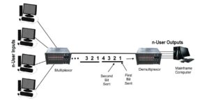
(C)Time Division Multiplexing (TDM)

  • This is another common method of multiplexing.
  • Here, separate time slots are allocated to each message/signals in an non-overlapping manner in the given time domain so that individual messages can be recovered from time synchronized switches.
  • Time Division Multiplexing (TDM) is another popular method of utilizing the capacity of a physical channel effectively.

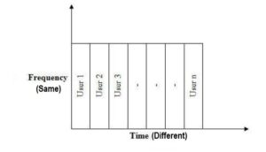
  • Here, each user of the channel is allotted a small time interval during which it may transmit a message. Thus the total time available in the channel is divided and each user is allocated a time slot. In this, data from each user is multiplexed into a frame which is transmitted over the channel.
  • In TDM, user’s messages are first buffered at the receiver end as they received and read from the buffer during its time slot to make a frame. Therefore each user can use the full channel bandwidth.
  • The channel capacity is fully utilized in TDM by interleaving a number of messages belonging to different users into one long message. This message sent through the physical link’s  channel that must be separated at the receiving end.
  • Here, Individual chunks of message sent by each user should be reassembled into a full message.
  • Here, Sharing of the signal is accomplished by dividing available transmission time on a medium among users. For example, in some countries, the individual stations have two logical sub channels: music and advertising. These two alternate in time on the same frequency first a burst of music, then a burst of advertising, then more music and so on. This situation is time division multiplexing.

  • Applications of TDM
    • The mechanism of TDM is applied in the PDH (Plesiochronous Digital Hierarchy) system, also known as the PCM (Pulse Code Modulation) systems.
    • In the synchronous digital hierarchy (SDH)/synchronous optical networking (SONET) network transmission standards.
    • TDM can be further extended into the time division multiple Channel (TDMA) scheme, where several stations connected to the same physical medium, for example sharing the same frequency channel, can communicate.
    • It is widely used in GSM telephone system.
  • Advantages of TDM
    • It uses a single link for data transmission.
    • It does not require precise carrier matching at both end of the links.
    • They Use full channel capacity.
    • The number of users can be expanded in a system at a low cost.
    • There is no need to include identification of the traffic stream on each packet.
  • Disadvantages of TDM
    • TDM can only be used for digital data multiplexing. This is because local loops produce analog signals, a conversion is needed from analog to digital in the end where all the individual local loops come together to be combined onto outgoing tracks.
    • The sensitivity to other user is very high and causes problems.
    • Initial set up cost of TDM is high.
    • It is more complex technically.

  • Types of TDM
    • There are two types of TDM –

(a) Synchronous TDM (b) Asynchronous/Statistical TDM

(a) Synchronous TDM:

Definition

    • In Synchronous TDM, each device has given same time slot/time slice to transmit the data over the single high speed link, irrespective of ignoring other factors such as the device has any data to transmit or not. Hence the name Synchronous TDM.

  • Features 
    • Here, each source device places its data onto the link when its time slot arrives.
    • Each device has given the time to access the link  turn by turn and they can use the link only their time slot has come.
    • If any device does not have data to send then its time slot remains empty.
    • In this, the various time slots are organized/grouped into frames and each frame consists of one or more time slots dedicated to each sending device. In another words, if there are sending /source devices, there will be slots in frame, if created i.e. one slot for each device.
    • Multiplexing is concerned with physical layer of the OSI reference model, not with data link layer.
  • Advantages :
    • It is a simpler method of TDM to implement because the process of multiplexing and demultiplexing is easier.
    • In Synchronous TDM, the time slots are reserved for each transmission, irrespective of whether it has any data to transmit or not.
    • Here, we mainly transmit digital signals, although the actual transmission may be digital or analog. In the latter case, the composite signal has to be converted into analog data by passing it through a modem.
    • It supports data sources with differing data rates to transmit. This could be done by assigning fewer slots to slower sources and more slots to the faster ones.
    • Here, a complete cycle of time slots is called a frame. At the receiving end, the frame is decomposed into the constituent data streams by sending the data in each time slot to the appropriate buffer.
    • The sequence of time slots allotted to a single data source makes up a transmission channel.
  • Disadvantages :
    • Synchronous TDM strictly follow the principle that the total speed of various input lines should not exceed but less or at least equal to the capacity of single high speed link/path otherwise transmission would be aborted.
    • This method can be inefficient because many time slots may have only silence/no data to transmit during their turn but that time slot is not used by other and finally wasted. 
    • As we know that in synchronous TDM data transmission can be quite wasteful. For example, as in a voice transmission, much of the bandwidth can be wasted because there are typically many periods of silence in a human conversation. Another example, could be, that of a time sharing system where many terminals are connected to a computer through the network. Here too, many of the time slots will not be used because there is no activity at the terminal. In spite of being comparatively simpler, synchronous TDM is therefore, often not an attractive option. 
    • We have already seen that the transmission in TDM must be synchronous because otherwise, all the data would be garbled and lost. [ To achieve synchronisation, at the physical layer, we have to ensure that each frame is synchronised to maintain the integrity of the transmission. One scheme to attain this is to add an extra bit of data to each frame. In succeeding frames, this extra bit forms a fixed pattern that is highly unlikely to occur naturally in the data. The receiver can then use this fact to synchronise the frames. Suppose each frame has n bits. Starting from anywhere, the receiver compares bit number 1, n+1, 2n+1 and so on. If the fixed data pattern is found, the frames are synchronised. Otherwise, the receiver commences to check bit number 2, n+2, 2n+2, … until it can determine whether the frames are in synchronization or otherwise. This continues till, it is able to synchronise the frames and can then start receiving the data from the various channels.
      Even after this, it is important to continue to monitor the fixed pattern to make sure that the synchronisation remains intact. If it is lost, the routine of re-establishing it needs to be repeated as before.
      The second problem in synchronising the transmission is the fact that there can be some variations between the different clock pulses from the different input streams.
      To take care of this, we can use the technique of pulse stuffing. Here, the multiplexed signal is of a rate that is a bit higher than that of the sum of the individual inputs. The input data is stuffed with extra pulses as appropriate by the multiplexer at fixed locations in the frame. This is needed so that the demultiplexer at the other, receiving, end can identify and remove these extra pulses. All the input data streams are thus synchronised with the single local, multiplexer clock. ] 

(b) Asynchronous/Statistical TDM:

    • Statistical TDM is normally used in place of synchronous TDM to overcome the disadvantage of it.
    • In this technique, time slots are not fixed as synchronous TDM rather here time slots are allocated dynamically to only those devices which have the data to send i.e. active workstations.
    • Here, total speed of the input lines can be greater than the capacity of the channel.
    • This multiplexing accepts the incoming data streams and creates a frame that contains only data with no empty slots.
    • In Asynchronous TDM, each slot contains an address part that identifies the source of the data.
    • This is a method where there are more devices than the number of time slots available. Here, each input data stream has a buffer associated with it. The multiplexer looks at the buffer of each device that provides the input data and checks to see if it has enough to fill a frame. If, there are enough, the multiplexer sends the frame. Otherwise, it goes to the next device in line and checks its input buffer. This cycle is continued indefinitely.

At the receiving end the demultiplexer decomposes the signal into the different data streams and sends them to the corresponding output line.

    • The multiplexer data rate is not higher than that of the sum of all the input devices connected to it. So statistical, TDM can make do with a lower transmission rate than needed by synchronous TDM, at the cost of more complexity.
    • They support higher throughput for the same available data rate of the multiplexer. This capability is easily realised during the normal, expected data transmission periods when the amount of data that the different input devices have available for transmission is, in fact, lower than the capacity of the multiplexing device. But the same attribute becomes a disadvantage during peak loads, where all or many of the devices may have data to transmit for a short time. In such a situation, the slack that was available to us for more efficient transmission is no longer present.
    • In this kind of scheme it is not known to us which input device will have data to send at a given time. So we cannot use a round robin positional scheme that was possible in synchronous TDM. Each frame has to be accompanied by information that will tell the demultiplexer which input device the frame belongs to, so that it can be delivered to the appropriate destination. This is the overhead of statistical TDM, besides increased complexity of equipment.
    • When we are sending input data from only one source at a time, the structure of a frame in it would need to have an address field for the source followed by the data for it. This is really the statistical TDM data frame. It would form the data part of a larger,
      enclosing HDLC frame if we are using HDLC as the transmission protocol. This frame would itself have various other fields. Such a scheme is also not as efficient as we can make it. This is because the quantum of data available from the source, in that time slot, may not be enough to fill the TDM sub frame. So, while it may be an adequate method if the load is not heavy, we also need to think of a method that can utilise available resources better.
    • It transfers more than one input data source transmit in a single TDM frame.
    • We would then need to have a more complex structure for the frame whereby, we would have to specify the different input devices in the frame followed by the length of the data field.
    • More sophisticated approaches could be used, in order to optimise the number of bits, we need to encode all this addressing and data information. For peak loads, there is need for some kind of buffering mechanism, so that, whenever there is excess input from the data sources that the multiplexer cannot immediately handle, it is stored until it can be sent. The size of the buffer needed will increase as the transmission capacity of the multiplexer decreases, as it will become more likely that an input data stream will not be transmitted immediately.
    • It will also depend on the average data rate of the input devices taken together. No matter what the buffer size we choose, there is always a non-zero probability that the buffer itself will overflow, leading to loss of data. If, the average data rate of all devices is close to the peak rate, then we are approaching a situation of synchronous TDM where we are not able to take advantage of periods of silence that is the basis of statistical TDM.

    (D)Code Division Multiplexing (CDM)

    • Here, users occupy the same frequency band but modulate their messages with different codes/coding techniques such as TDMA FDMA CDMA when used for multiple access TDMA, FDMA, e.g., GSM, FM, AM, Wireless networks. 

    The multiple access is that where we can allow several transmitters to send information simultaneously over a single communication channel and it allows several users to share a band of frequencies (or bandwidth). CDMA uses spread-spectrum technology and a special coding scheme (where each transmitter is assigned a code generally pseudorandom code) to allow multiple users to be multiplexed over the same physical channel.

    By contrast, time division multiple access (TDMA) divides access by time, while frequency-division multiple access (FDMA) divides it by frequency. CDMA is a form of spread-spectrum signaling, since the modulated coded signal has a much higher data bandwidth than the data being communicated. This allows more users to communicate on the same network at one time than if each user was allotted a specific frequency range. As we know that CDMA is a digital technology, so analog signals must be digitized before being transmitted on the network.

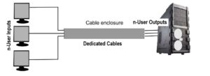
    (E)Space Division Multiplexing (SDM)

    • In this method, when we want to transmit multiple messages from multiple users through any of the communication media, this uses many separate wires into a common cable enclosure (such as a cable that has, for example, 100 twisted pairs inside it can support 100
      channels.)
    • It does not require any multiplexing equipment hence it is really not a multiplexing technique rather it only appears like as multiplexing.
    • It is usually combined with other multiplexing techniques to better utilize the individual physical channels. For example, if there are six persons in the office and all of them want to talk at the same time, this will give rise to interference between the conversations. To reduce the interference they may divide themselves into three groups of two, such that the conversation is between each pair of people. If the pairs continue talking whilst sitting next to each other, the interference would still be present. The best way for each pair to converse with minimal interference would be to sit a few feet away from the other pairs (within the same room) and converse.
    • Space Division Multiplexing is the multiplexing technique in which both the time and frequency can be reused by transmitting our information through a parallel set of channels.

    • In wired communication, space-division multiplexing simply implies different point-to- point wires for different channels.

    Examples include an analogue stereo audio cable, with one pair of wires for the left channel and another for the right channel, and  a multipair telephone cable usually employed to provide PSTN connections in different homes.

    Another example is a switched star network such as the analog telephone access network (although inside the telephone exchange or between the exchanges, other multiplexing techniques are typically employed).

    • In wireless communication, space-division multiplexing is achieved by multiple antenna elements forming a phased array antenna.

    Examples are multiple-input and multiple-output (MIMO), single-input and multiple-output (SIMO) and multiple-input and single output (MISO) multiplexing.

    References : IGNOU’s computer science blocks


    0 Comments

    Leave a Reply

    Your email address will not be published. Required fields are marked *

    This site uses Akismet to reduce spam. Learn how your comment data is processed.