Encoding
-
Introduction
- Encoding is the broader term, and modulation is a subset of encoding.
- All modulation is encoding, but not all encoding is modulation.
- Encoding is the general process of converting data into a signal suitable for transmission or storage.
- Modulation is a special case of encoding in which a carrier signal is always used and varied to transmit information.
-
Definition
- Encoding schemes define the methods used to convert digital or analog data into signals suitable for transmission over a communication medium.
-
Characteristics
- Encoding ensures that data can be transmitted efficiently, accurately, and reliably from the sender to the receiver.
- In computer networks, digital-to-digital encoding is most commonly used.
- The encoding mechanism may(in modulation) or may not use a carrier signal. Encoding, in the strict data communications sense, refers to conversions that do not require a carrier signal.
-
Purpose of Encoding Schemes
- Encoding schemes are used to:
- Represent binary data (0s and 1s) as electrical, optical, or radio signals
- Maintain synchronization between sender and receiver
- Detect errors and reduce signal distortion
- Optimize bandwidth usage
- Encoding schemes are used to:
-
Types of Encoding Schemes
- In data communications, the process of converting data into signals can be classified into four categories. Some of these processes are called encoding, while others are specifically called modulation. Thus, encoding schemes are broadly classified into –
- analog data-to-analog signal (Encoding, but actually Modulation[Analog Modulation])
- digital data-to-analog signal (Encoding but actually Modulation[Digital Modulation])
- analog data-to-digital signal (Encoding only)
- digital data-to-digital signal (Encoding only)
- The process of encoding is performed in the following ways –
- Analog Data -> Digital Signal
- This is done in 2 ways : (i) PCM and (ii) DM.
- Digital Data -> Digital Signal
- This is done in 3 ways : (i) Unipolar, (ii) Polar, and (iii) Bipolar.
- Analog Data -> Digital Signal
- In data communications, the process of converting data into signals can be classified into four categories. Some of these processes are called encoding, while others are specifically called modulation. Thus, encoding schemes are broadly classified into –
Analog Data -> Digital Signal :
-
- This is an encoding scheme (not modulation, as named) that is done in two ways: PCM (Pulse Code Modulation) and Delta Modulation(DM).
- Although PCM (Pulse Code Modulation) and Delta Modulation are classified as analog-to-digital encoding techniques, not modulation techniques, but the word “modulation” is used in their names for historical and functional reasons, not because they are carrier-based modulation like AM or FM.
- In PCM and Delta Modulation
- The amplitude of the analog signal is sampled
- The samples are quantized
- The values are encoded into binary form
Here, the signal is still being varied in the form of pulses, so early researchers used the word modulation.
-
- Also, PCM was developed for telephony systems long before digital networking terminology was standardized. At that time:
- Any transformation of a signal was loosely called modulation
- The strict distinction between encoding and modulation came later
- Also, PCM was developed for telephony systems long before digital networking terminology was standardized. At that time:
So the name stuck, even though the classification changed.
-
- Actually, PCM and Delta Modulation
- Do not use a carrier signal
- Directly convert analog data into digital pulses
- Actually, PCM and Delta Modulation
Therefore, they are technically encoding techniques. Hence, they are classified as analog-to-digital encoding, despite the name.
(i) Pulse Code Modulation (PCM)
Definition
-
-
- Pulse Code Modulation (PCM) is a digital modulation technique used to convert analog signals into digital forms for transmission or storage.
-
Features
-
-
- It is widely used in various applications, including telecommunications, audio recording, and data transmission.
- PCM works by sampling the analog signal at regular intervals and quantizing each sample to a binary code.
-
Advantage
-
-
- Pulse Code Modulation (PCM) offers a robust, reliable, and flexible method for digitizing analog signals, providing advantages such as noise reduction, improved signal integrity, compatibility, and enhanced signal processing capabilities, which make it widely used in various applications.
- Pulse Code Modulation (PCM) offers several advantages over analog signal representation and other modulation techniques. Some key advantages of PCM are:-
- Low Noise and Distortion: PCM offers a high signal-to-noise ratio, which means the digital representation of the analog signal is less susceptible to noise and distortion compared to analog transmission. This is because PCM quantizes the signal at discrete levels, reducing the impact of noise during transmission or storage. Additionally, the use of error detection and correction techniques in digital systems further enhances the accuracy and reliability of PCM.
- Signal Integrity: PCM preserves the integrity of the original analog signal. Once the signal is converted into digital form, it can be transmitted or stored without degradation, as long as the digital representation is maintained. This is particularly useful for long-distance transmission or archival purposes, where analog signals are prone to deterioration.
- Compatibility and Interoperability: PCM is a widely adopted standard, making it highly compatible and interoperable with various digital systems and devices. This allows PCM-encoded data to be easily processed, transmitted, and decoded by different equipment, regardless of the specific implementation or manufacturer.
- Flexibility and Scalability: PCM offers flexibility in terms of resolution and sampling rate. By increasing the number of bits used for quantization, the resolution of the PCM system can be enhanced, resulting in higher fidelity and accuracy. Similarly, adjusting the sampling rate allows for capturing a wider frequency range or preserving more details in the analog signal.
- Signal Processing Capabilities: Once an analog signal is converted into digital form through PCM, it becomes amenable to a wide range of digital signal processing techniques. These techniques include filtering, compression, encryption, and various algorithms for analyzing, modifying, or extracting information from the signal. PCM facilitates advanced signal processing operations that are not easily achievable with analog signals.
- Error Detection and Correction: PCM systems can incorporate error detection and correction techniques to ensure data integrity. By adding redundancy in the encoded data and employing error detection and correction algorithms, PCM can detect and recover from transmission errors, ensuring the accuracy of the received signal.
- Immunity to Analog Signal Interference: PCM is immune to analog signal interference, such as crosstalk, electromagnetic interference, and amplitude fluctuations. As the analog signal is converted into a digital format, these analog interferences are not carried forward to the digital representation, resulting in improved signal quality.
-
Disadvantage
It also has some limitations and disadvantages. A few of them are:-
-
-
-
- Bandwidth Requirements: PCM requires relatively high bandwidth to transmit or store digital data accurately. The required bandwidth is determined by the sampling rate used in PCM. Higher sampling rates result in larger data sizes, demanding more bandwidth for transmission or storage. This can be a limitation in situations where there are constraints on available bandwidth, such as in certain communication systems or storage devices.
- Storage and Transmission Overhead: PCM-encoded data tends to have larger file sizes compared to analog signals. This can lead to increased storage requirements, especially when dealing with large amounts of data or for applications with limited storage capacity. Similarly, transmitting PCM-encoded data over communication channels consumes more bandwidth compared to analog signals, which may be a limitation in scenarios with limited channel capacity.
- Quantization Noise: During the quantization process in PCM, the analog signal is divided into discrete levels. The quantization process introduces quantization noise, which is a form of distortion. This noise arises from the rounding errors associated with representing the continuous analog signal with a limited number of quantization levels. Although the noise can be minimized by using a higher number of bits for quantization, there is always a trade-off between the desired level of accuracy and the introduced quantization noise.
- Limited Dynamic Range: The dynamic range of PCM is determined by the number of quantization levels used. Increasing the number of levels enhances the dynamic range, allowing for a more precise representation of the analog signal. However, there is a practical limit to the number of quantization levels due to constraints on storage capacity, bandwidth, and the cost of the equipment. This limited dynamic range can result in the loss of subtle details or reduced accuracy in representing signals with wide amplitude variations.
- Clock Synchronization: PCM systems rely on accurate clock synchronization between the transmitter and receiver for proper sampling and reconstruction of the analog signal. Any deviation or instability in the clock synchronization can introduce timing errors, resulting in signal distortion or loss. Ensuring precise clock synchronization can be a challenge in certain systems, especially in scenarios with multiple devices or long-distance transmission.
- Complexity and Cost: Implementing PCM systems requires sophisticated hardware and signal processing algorithms. The analog-to-digital converter (ADC) and digital-to-analog converter (DAC) used in PCM systems can be complex and expensive, especially for high-resolution or high-speed applications. The additional signal processing and error correction techniques employed in PCM systems also contribute to the complexity and cost of the overall system.
-
-
Use/Application
-
-
- Pulse Code Modulation provides a convenient way to digitize analog signals accurately, allowing for efficient transmission, storage, and processing of audio, voice, and other analog data.
-
(ii) Delta Modulation (DM)
Definition
-
-
- This is a modulation technique that converts analog data into its respective digital signal.
- When the sampling rate is much higher, and the step size after quantization is of a smaller value Δ in a modulation, such a modulation is termed delta modulation.
-
Features
-
-
- It is an analog-to-digital and digital-to-analog signal conversion technique.
- It is a 1-bit quantizer.
- An oversampled input is taken to make full use of the signal correlation.
- It supports the very easy design of the modulator and the demodulator.
- In delta modulation, the amplitude of the speech signal does not exceed the maximum sinusoidal amplitude.
- The input sequence is much higher than the Nyquist rate.
- The design of the modulator and the demodulator is simple.
- The step size is very small, i.e., Δ (delta).
- The bit rate can be decided by the user.
-
Advantage
-
-
- Here, the electronic circuit requirement for modulation at the transmitter and for demodulation at the receiver is substantially simpler compared to PCM.
- DM is the simplest form of conversion.
- The quantization design is simple.
- The quality is moderate.
- The signaling rate and bandwidth of the delta modulation are less than the PCM technique.
- This involves a simpler implementation.
-
Disadvantage
-
-
- There exists some noise in DM.
- The modulator part shows overload when the slope of the signal is too high.
- High bit rate.
- It requires a predictor circuit, and hence it is considered very complex.
- Its practical usage is limited.
-
Use/Application
-
-
- This technique is used for the transmission of voice information where quality is not of primary importance.
-
Digital Data -> Digital Signal
-
- This encoding scheme converts digital data into a digital signal.
- In computer networks, this digital-to-digital encoding is most commonly used. Some common Examples are :
- A simple example is when we send digital data from a computer to a printer in the form of digital signals for printing purposes, for short distances of transmission over the printer cable in the form of a series of digital pulses.
- Another example of such encoding is the transmission of digital data between computer and computers in local area networks such as Ethernet.
- This kind of encoding is done in three ways:-
(i) Unipolar
Definition
-
-
-
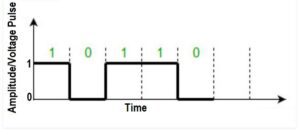
- Unipolar is the simplest encoding mechanism to encode digital data(such as 10110010) into its respective digital signal(digital graph form) for transmission over the communication medium.
-
-
Features
-
-
-
- As the name suggests, in this, there is only one polarity used in the transmission of the pulses, i.e., a positive pulse may be represented as 1, and a zero voltage can be represented as 0.
- This type of encoding is known as Unipolar encoding, as it uses only one polarity, i.e. positive pulse for 1.
- In this digital transmission, the transmitter sends the digital data in the form of digital signal/voltage pulses over the medium or link, such as a wire or cable.
- In this unipolar encoding, ‘1’ is considered a high voltage, and ‘0’ is considered a zero voltage.
-
-
Advantage
-
-
-
- The unipolar encoding uses less energy comparatively and also has a low cost in its implementation.
-
-
Disadvantage
-
-
-
- This method is rarely used in real practice because of the inherent problems of the method, i.e., unipolar encoding faces two types of inherent problems that make this scheme less usable. These are:-
- Synchronization:
- This method is rarely used in real practice because of the inherent problems of the method, i.e., unipolar encoding faces two types of inherent problems that make this scheme less usable. These are:-
-
-
-
-
-
-
-
- As we know, for successful data transmission in any digital communication system, the transmitter and receiver devices must have to be synchronized; otherwise, all the information may be lost.
-
-
-
-
-
-
-
-
- DC Component:
-
-
-
-
-
-
-
-
- Another problem with unipolar encoding is that the average voltage of the signal is non-zero. This causes a direct current component to exist in the signal. This cannot be transmitted through some components of the circuit, causing difficulties in reception.
-
-
-
-
(ii) Polar
Definition
-
-
-
- Polar encoding is another important method of encoding in which digital data is converted into its respective digital signal by using two voltage levels, positive and negative, to represent 0 and 1.
-
-
Features
-
-
-
- Unlike unipolar schemes, the polar methods use both a positive as well as a negative voltage level to represent the value of the bit, i.e., a positive voltage may represent a 1 and a negative voltage may represent a 0, or the other way around.
- Because both positive and negative voltages are present, the average voltage is much lower than in the unipolar case, hence removing the problem of the DC component in the signal. Thus, Polar encoding eliminates some of the DC residual problems of Unipolar.
-
-
Advantage
-
-
-
- The power consumed in polar encoding to transmit the signal is one-half that of a unipolar signal.
-
-
Disadvantage
-
-
-
- Unlike Bipolar encoding, it has only two limited voltage states, 0 and 1.
-
-
Types of Polar
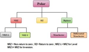
(a) NRZ (Non-return to Zero)
-
-
-
- Non-return to Zero (NRZ) is a polar encoding scheme that uses a positive as well as a negative voltage to represent the bits.
- Here, a zero voltage will indicate the absence of any communication at the time.
- NRZ is further divided into two types/variants based on level and inversion. These are –
-
-
(i) NRZ-L :
-
-
-
-
- In NRZ-L (for level) encoding, it is the levels themselves that indicate the value of the bit, i.e., a positive voltage for a 1 and a negative voltage for a 0.
- Regarding synchronization, NRZ-L is not well placed to handle it if there is a string of 0’s or 1’s in the transmission.
-
-
-
(ii) NRZ-I :
-
-
-
-
- In NRZ-I (inversion) encoding, an inversion of the current level indicates a 1, while a continuation of the level indicates a 0.
- Regarding synchronization, NRZ-I is better off here as a 1 is signaled by the inversion of the voltage. So every time a 1 occurs, the voltage is inverted, and we know the exact start of the bit, allowing the clock to be synchronized with the transmitter. However, this advantage does not extend to the case where there is a string of 1’s. We are still vulnerable to losing synchronization in such a case.
-
-
-
(b) RZ (Return to Zero)
-
-
-
- Return to Zero (RZ) is a method that allows for synchronization after each bit. This is achieved by going to the zero level midway through each bit. So a 1 bit could be represented by the positive to zero transition and a 0 bit by a negative to zero transition.
- Here, at each transition to zero, the clocks of the transmitter and receiver can be synchronized.
- This requires a higher bandwidth.
-
-
(c) Biphase
-
-
-
- This is the third polar method of encoding, in which (while in RZ, the signal goes to zero midway through each bit), the opposite polarity midway through RZ occurs through each bit. These transitions help in synchronization
- Biphase again has three types/flavors:-
-
-
(i) Manchester Encoding :
-
-
-
-
- Here, there is a transition in the middle of each bit that achieves synchronization. A 0 is represented by a negative to positive transition, while a 1 is represented by the opposite.
-
-
-
(ii) Differential Manchester Encoding :
-
-
-
-
- In the Differential Manchester method, the transition halfway through the bit is used for synchronization as usual, but a further transition at the beginning of the bit represents the bit itself. There is no transition for a 1, and there is a transition for a 0, so that a 0 is actually represented by two transitions.
-
-
-
(iii) Bipolar Encoding
Definition
-
-
-
-
-
- Bipolar encoding is a telecommunication technology that is a type of return-to-zero line code, where two non-zero values are used so that the three values are +, −, and zero.
-
-
-
-
Features
-
-
-
-
-
- This encoding method uses three levels, with a zero voltage representing a 0 and a 1 being represented by positive and negative voltages, respectively. This way, the DC component is done away with because every 1 cancels the DC component introduced by the previous 1.
- In bipolar encoding, a real 1 bit is represented by the opposite voltage level every time; there is no possibility of confusing the 0 with a 1.
- This kind of transmission also ensures that every 1 bit is synchronized.
-
-
-
-
Types of Bipolar
(i) Alternate Mark Inversion (AMI):
-
-
-
-
-
- The simplest bipolar method is called Alternate Mark Inversion (AMI).
- The problem with Bipolar AMI is that synchronization can be lost in a long string of 0’s.
-
-
-
-
(ii) High-Density Bipolar 3 (HDB3):
-
-
-
-
-
- It is one of the ways of synchronizing 0’s, which was the demerit of AMI.
- This method synchronizes the 0’s by changing the pattern after every four consecutive 0’s. The change is to represent the 0 by a positive or negative signal instead of the zero voltage. Now, how do we prevent this from being wrongly interpreted as a 1? It is done by using the same voltage level as was used for the previous 1.
- HDB3 changes the pattern of four 0’s depending on the number of 1’s since the last such substitution and the polarity of the last 1. If the number of 1’s since the last substitution is odd, the pattern is violated at the fourth 0. So if the previous 1 was positive, the 0 is also made positive to avoid confusion with a 1. If the number of 1’s
Since the last substitution is even, the first and fourth zeroes have a pattern violation.
-
-
-
-
(iii) 8-Zero Substitution (B8ZS):
-
-
-
-
-
- It is another method of achieving 0 synchronizations is called 8-Zero Substitution (B8ZS). Here, a string of 8 zeroes is encoded depending on the polarity of the previous actual 1 bit that occurred. If the previous 1 was sent as a negative voltage, the zeroes are sent as three 0’s followed by a negative, positive, zero, positive, and negative voltage sequence. A similar but opposite pattern violation is performed for the case where the last 1 was positive. This way, a deliberate pattern violation is used to achieve synchronization.
-
-
-
-
Advantage
-
-
-
-
-
- It is a simple line coding type.
- The bipolar encoding uses a lower bandwidth than unipolar and polar.
- Signal droop does not occur in bipolar type, unlike unipolar and polar.
-
-
-
-
Use/Application
-
-
-
-
-
- A bipolar encoding scheme is used to solve the problem of synchronizing sequential 0s, especially for long-distance transmission.
-
-
-
-
Modulation
(Click this Link for the difference between Modulation & Encoding)
Introduction of Modulation
- As we know, in normal communication, signals lose their strength/energy slowly as they travel through the medium over large distances. To send these transmitting message signals effectively over long distances, we use the modulation technique. At the receiver end, after receiving the signal, we finally convert it into the original frequency band (baseband) through demodulation.
- The term modulation simply meant “varying a signal” to represent information.
-
Carrier Signal(Medium- Air/Cable) :
- The carrier signal conveys the data/message/information.
- It is an electromagnetic wave or pulse having a steady frequency.
- Carrier signals are high-frequency signals in sinusoidal pulse form.
- The carrier signal is modulated by the modulating or information signal.
-
Modulating Signal(Data/Message) :
- It is the original signal/message we want to send/modulate with the carrier signal.
- In other words, it is the signal that contains a message to be transmitted.
- Modulating signals are usually low-frequency signals.
-
Modulated Signal(Data or Message in Air/Cable) :
- It is the mixing of signals of both carriers and modulating signals using the modulation process.
- This signal has a new property that is different from the carrier and modulating signal.
Definition of Modulation
- Modulation is one of the most important data transmission techniques that helps to transmit data from the source to the destination through a medium.
- It is the process of changing some physical characteristics (such as amplitude, frequency, or phase) of a carrier wave in accordance with the intensity of the signal is known as modulation.
Features/Characteristics of Modulation
- It helps in data transmission, usually for long distances through an analog medium (air/cables).
- Modulation is used to transmit data mainly in air/telephone lines/optical fibers.
- The modulation mechanism always uses a carrier signal to transmit data.
Advantages of Modulation
- The modulation process can shift the frequency spectrum of a message/modulating signal near a band that is better suited to the channel for easy transmission.
- Modulation permits the use of multiplexing in data communication.
- Modulation (frequency modulation) can provide some control over noise and interference.
- Modulation is usually done without loss of information.
Disadvantages of Modulation
- It is an extra process implemented on analog/digital data during communication.
- It requires/uses an extra device.
Types of Modulation
There are two types of Modulation –
Analog Modulation (Analog Data -> Analog Signal)
- Analog modulation is the simplest form of modulation.
- Analog modulation is the conversion of analog data into an analog signal.
- Analog modulation is done by a device called a modem through a process of Modulation. Modem performance/modulation consists of two processes called Modulating and Demodulating by the Modulator and Demodulator components of the Modem.
- Analog modulation is used when the information signal is analog in nature, such as voice or music.
- Analog modulation shifts the original signal’s baseband frequency into the broadband frequency.
- In analog modulation, one of the characteristics of a high-frequency carrier signal is varied continuously according to the analog message signal.
- Analog modulation is mostly suitable for data transmission in an analog medium/environment.
- Analog modulation is done in two ways: (i) Amplitude Modulation, (ii) Angle Modulation.
Amplitude Modulation (AM)
Definition
-
- Amplitude modulation is a technique used in electronic communication, most commonly for transmitting information via a high-frequency carrier wave.
- Features
- AM works by varying the strength/amplitude of the transmitted signal in relation to the information being sent.
- In amplitude modulation, the amplitude of the carrier signal is varied in proportion to the amplitude of the analog message signal, while the frequency and phase remain constant.
Advantage
-
- The transmission coverage area of an AM Receiver is wider than FM receiver because of atmospheric propagation.
- AM supports long-distance propagation because of its high power.
- An AM circuit is the cheapest and least complex.
- AM can be easily demodulated using a Diode Detector.
Disadvantage
-
- It is very sensitive to noise, and hence the quality & performance are very weak.
- The signal of AM is not stronger than FM when it propagates through an obstacle.
- Only one sideband of AM transmits the Information Signal, so it loses power on the other sideband and carrier. Hence, the power efficiency of the Amplitude Modulation is very poor.
Angle Modulation
- The main characteristic of the angle modulation is that the amplitude of the carrier frequency is maintained constant, whereas the frequency or phase is changed.
- Angle Modulation has two forms –
(i) Frequency Modulation (FM)
Definition
-
-
- Frequency modulation is the technique in which the frequency of the carrier wave is changed (remaining amplitude and phase constant) in accordance with the amplitude of the modulating signal.
-
Features
-
-
- FM is widely used in a variety of radio communication applications.
- In frequency modulation, the frequency of the carrier signal is varied according to the amplitude of the message signal, while the amplitude of the carrier remains constant.
-
Advantage
-
-
- This technique is resilient towards noise (noise hater) and is hence utilized by the broadcasting industry.
- Using this technique, stereophonic transmission is possible.
- This technique does not require linear amplifiers in the transmitter because only frequency changes are required to be carried out. Hence, no need for amplifiers in the transmitter.
- It has comparatively greater efficiency than many other modes.
-
Disadvantage
-
-
- It requires a larger bandwidth.
- It needs to be operated at very high-frequency bands.
- The process of demodulation in this process is complex and hence requires a more complicated demodulator hence more expensive.
-
(ii) Phase Modulation(PM)
Definition
-
-
- In phase modulation, the phase of the carrier wave is changed (remaining amplitude and frequency constant) in accordance with the amplitude of the modulating frequency.
-
Features
-
-
- Phase modulation is a form of analog modulation.
- Phase modulation works by modulating the phase of the signal, i.e., changing the rate at which the point moves around the circle.
- In phase modulation, the phase of the carrier signal is varied in accordance with the amplitude of the message signal, while the amplitude and frequency remain unchanged.
- When phase modulation is applied to a signal, there are frequency changes and vice versa. Phase and frequency are inseparably linked, as phase is the integral of frequency. Due to these reasons, frequency modulation can be changed into phase modulation when required.
-
Advantage
-
-
- Its modulation and demodulation processes are comparatively easier than frequency modulation.
-
Disadvantage
-
-
- PM is not very widely used for radio transmissions because it tends to require more complex receiving hardware, and there can be ambiguity problems in determining whether, for example, the signal has changed phase by +180° or -180°.
-
Use/Application
-
-
- This method is used for producing radio signals used in a variety of radio communications applications.
- PM is used in digital music synthesizers such as the Casio CZ synthesizers or to implement FM Synthesis in digital synthesizers such as the Yamaha DX7.
-
Digital Modulation (Digital Data -> Analog Signal)
Introduction
-
- Digital modulation is done by a device called a ‘Codec’ through a process called Encoding.
- Codec performs/encoding consists of two processes called Coding and Decoding by the Encoder and Decoder components of the Codec, respectively.
Definition
-
- Digital modulation refers to the process of modulating digital data onto an analog carrier signal for transmission in communication systems.
Features
-
- Digital modulation is suitable for data transmission in a digital medium/environment.
- Digital modulation techniques convert digital data into an analog carrier signal by varying one or more properties of the carrier. Since a carrier signal is used, the process is called modulation, not encoding.
- Digital modulation is used when the information signal is digital in nature, such as binary data. In digital modulation, the carrier signal is varied in discrete steps according to digital data (0s and 1s).
- Although digital techniques map digital bits (0s and 1s) onto signal changes, the presence of a carrier signal makes them modulation, not encoding.
- It involves converting discrete digital signals into continuous analog waveforms that can be transmitted over various channels, such as wired or wireless mediums.
- Digital modulation schemes are widely used in modern communication systems to achieve efficient and reliable data transmission.
- There are several commonly used digital modulation schemes- ASK, FSK, PSK, QAM, etc.
- The choice of digital modulation scheme depends on various factors such as the desired data rate, bandwidth efficiency, noise robustness, and implementation complexity.
- The robustness, efficiency, and flexibility of digital modulation contribute to improved reliability and performance in data transmission.
Advantages
Digital modulation offers several advantages over analog modulation in communication systems:-
-
- Improved Noise Immunity: Digital modulation schemes are more resilient to noise and interference compared to analog modulation. Since digital signals are discrete and have predefined levels or states, they can be accurately detected and decoded even in the presence of noise. Error detection and correction techniques can be applied to further enhance the reliability of digital communication.
- Efficient Use of Bandwidth: Digital modulation allows for efficient utilization of the available bandwidth. By using techniques such as multi-level modulation (e.g., QAM) or multi-carrier modulation (e.g., Orthogonal Frequency Division Multiplexing[OFDM]), digital signals can transmit more data per unit of bandwidth compared to analog signals. This enables higher data rates and improved spectral efficiency in communication systems.
- Better Signal Quality: Digital modulation provides better signal quality and fidelity compared to analog modulation. Digital signals can be regenerated and restored with minimal degradation, ensuring accurate reproduction of the original data. This is particularly advantageous in long-distance transmission or when the signal needs to traverse multiple amplifiers or processing stages.
- Ease of Integration with Digital Signal Processing: Digital modulation seamlessly integrates with digital signal processing techniques. Once the analog signal is converted to digital, it can be processed using a wide range of digital signal processing algorithms for tasks such as error correction, equalization, channel coding, and modulation/demodulation. This flexibility allows for sophisticated signal processing techniques to be applied, leading to enhanced performance and adaptability.
- Compatibility with Data Compression and Encryption: Digital modulation is compatible with data compression and encryption techniques. Digital data can be compressed to reduce the amount of transmitted information, thereby saving bandwidth. Encryption algorithms can also be applied to secure digital data, ensuring confidentiality and integrity during transmission. These capabilities enable efficient and secure data communication in digital systems.
- Flexibility and Versatility: Digital modulation offers flexibility and versatility in adapting to different communication scenarios and requirements. The same digital modulation scheme can be used across various communication standards, enabling interoperability and simplifying system design. Additionally, digital modulation schemes can be easily upgraded or modified to support higher data rates, different channel conditions, or new features, providing scalability and future-proofing for communication systems.
Disadvantages
While digital modulation offers several advantages, there are also some disadvantages:
-
-
- Increased Bandwidth Requirements: Digital modulation schemes often require larger bandwidth compared to analog modulation schemes to transmit the same amount of information. This is mainly due to the need to transmit additional information to represent digital symbols accurately. The increased bandwidth requirement can be a limitation in certain applications where bandwidth is limited or expensive.
- Complexity and Processing Overhead: Digital modulation involves more complex signal processing techniques compared to analog modulation. The encoding and decoding processes require additional computational resources and processing power. This increased complexity can impact the cost, power consumption, and implementation complexity of the communication system.
- Synchronization and Timing Challenges: Digital modulation schemes require precise synchronization and timing recovery at the receiver to accurately decode the transmitted symbols. Variations in timing, clock drift, or synchronization errors can lead to symbol errors and degradation in the received signal quality. Ensuring accurate synchronization can be challenging, especially in high-speed or multi-user communication systems.
- Vulnerability to Nonlinear Distortions: Digital modulation schemes can be more susceptible to nonlinear distortions introduced by components in the transmission path, such as power amplifiers. Nonlinearities can cause intermodulation and harmonic distortions, leading to signal degradation and increased bit error rates. Careful design and compensation techniques are required to mitigate the impact of nonlinear distortions in digital modulation systems.
- Limited Performance in Low Signal-to-Noise Ratio (SNR) Conditions: While digital modulation schemes exhibit good noise immunity, their performance can degrade in low SNR conditions. As the SNR decreases, the bit error rate (BER) increases, impacting the reliability and quality of the received data. In contrast, analog modulation schemes may provide better performance in extremely low SNR environments.
- Complexity in High-Order Modulation Schemes: Higher-order digital modulation schemes, such as higher-order QAM or PSK, offer higher data rates but are more susceptible to errors caused by noise, interference, and channel impairments. The receiver complexity increases exponentially with the order of modulation, making the implementation and decoding more challenging.
-
Use/Applications
-
- The different digital modulation schemes are widely adopted in modern communication systems, including wireless communication, satellite communication, digital broadcasting, and broadband access networks.
Types of Digital Modulation
There are 4 ways to perform digital modulation –
(i) Amplitude Shift Keying (ASK)
Definition
-
-
- Amplitude-shift keying (ASK) is a form of analog modulation that represents digital data in the form of analog signals as variations in the amplitude of a carrier wave. The frequency and Phase of the carrier are kept constant.
-
Features
-
-
- ASK modulation uses a finite number of amplitudes (to represent digital data), each assigned a unique pattern of binary values.
- In amplitude shift keying, the amplitude of the carrier signal is changed between discrete levels to represent binary data.
- Usually, each amplitude encodes an equal number of bits. Each pattern of bits forms the symbol that is represented by the particular amplitude.
- Like Amplitude Modulation, ASK is also linear and sensitive to atmospheric noise, distortions, propagation conditions on different routes in PSTN (Public Switched Telephone Network), etc.
- For LED transmitters, binary 1 is represented by a short pulse of light, and binary 0 by the absence of light. Laser transmitters normally have a fixed “bias” current that causes the device to emit a low light level. This low level represents binary 0, while a higher-amplitude light wave represents binary 1.
-
Advantage
-
-
- Both ASK modulation and demodulation processes are relatively inexpensive.
- Today, even more sophisticated forms of encoding schemes have been developed & used, which represent data in groups using additional amplitude levels. For instance, a four-level encoding scheme can represent two bits with each shift in amplitude; an eight-level scheme can represent three bits, and so on.
-
Disadvantage
-
-
- These forms of amplitude-shift keying require a high signal-to-noise ratio for their recovery, as by their nature, much of the signal is transmitted at reduced power.
-
Use/Application
-
-
- The simplest and most common form of ASK operates as a switch, using the presence of a carrier wave to indicate a binary one and its absence to indicate a binary zero. This type of modulation is called on-off keying and is used at radio frequencies to transmit Morse code.
- The ASK technique is also commonly used to transmit digital data over optical fiber.
-
(ii) Frequency Shift Keying (FSK)
Definition
-
-
- Frequency-shift keying (FSK) is a form of modulation scheme in which digital information is transmitted through discrete frequency changes of a carrier wave. Here, the Phase and Amplitude of the carrier wave are kept constant.
-
Features
-
-
- It is one of the forms of modulation techniques to increase the frequency characteristics of the input binary signal.
- In frequency shift keying, the frequency of the carrier signal is shifted between discrete values to represent digital data.
- FSK is preferred over ASK(leads to wastage of power).
- BFSK :
- The simplest FSK is called binary FSK (BFSK).
- BFSK uses a pair of discrete frequencies to transmit binary (0s and 1s) information. With this scheme, the “1” is called/represented as the mark/dense frequency, and the “0” is called the space/gap frequency.
- The modulating signal and the carrier signal frequency are fed to the frequency modulator (FSK Transmitter) circuitry, and correspondingly, the output is transmitted in the form of a signal with a varied frequency.
-
Advantage
-
-
- It shows more noise immunity than the ASK.
- It supports a high data transmission rate.
- It is a simple process to construct the circuit.
- It shows zero amplitude variations.
- It has fewer errors.
- It has a high SNR (signal-to-noise ratio) value.
- Error-free reception can be possible with FSK.
- Useful in high-frequency radio transmissions.
- Preferably in high-frequency communications.
-
Disadvantage
-
-
- It consumes more bandwidth than the ASK and PSK.
- FSK is used only in low-speed modems (1200 bits/sec) due to more bandwidth consumption, i.e., this FSK has a finite data rate and consumes more bandwidth.
-
Use/Application
-
-
- FSK modulation technique is used to achieve error-free communication in a few digital applications.
-
(iii) Phase Shift Keying (PSK)
Definition
-
-
- Phase-shift keying (PSK) is a form of modulation scheme that communicates the data by changing or modulating the phase of the carrier wave. The frequency and Amplitude of the carrier are kept constant.
-
Features
-
-
- PSK uses a finite number of phases, each assigned a unique pattern in the form of a binary code. Each pattern of bits forms the symbol that is represented by the particular phase.
- This process determines the phase of the received signal and maps it back to the symbol it represents, thus recovering the original data.
- In phase shift keying, the phase of the carrier signal is changed to represent digital data. Common forms include BPSK and QPSK.
- Like any other form of shift keying, there are clear-cut defined states or points that are used for signaling the data bits. The basic form of binary phase shift keying is known as Binary Phase Shift Keying (BPSK), or it is occasionally called Phase Reversal Keying (PRK). A digital signal alternating between +1 and -1 (or 1 and 0) will create phase reversals, i.e., 180-degree phase shifts as the data shifts state.
- Since this modulation scheme depends on the difference between successive phases, therefore, it is termed differential phase-shift keying (DPSK). DPSK can be significantly simpler to implement than ordinary PSK since there is no need for the demodulator to have a copy of the reference signal to determine the exact phase of the received signal.
- This requires the receiver to be able to compare the phase of the received signal to a reference signal.
- In this system, the demodulator determines the changes in the phase of the received signal rather than the phase (relative to a reference carrier wave) itself.
-
Advantage
-
-
- PSK allows information to be carried with a radio communications signal more efficiently compared with FSK.
- It is less vulnerable to faults when we evaluate with ASK modulation & occupies a similar bandwidth to ASK.
-
Disadvantage
-
-
- In PSK, the receiver cannot know the exact phase of the transmitted signal to determine whether it is in a mark or space condition. This is because it is not possible, even if the transmitter and receiver clocks were accurately linked. After all, the path length would determine the exact phase of the received signal.
- In a basic system, this process is not used because it may be possible to lose synchronization if a long series of zeros is sent. This is because the phase will not change state for this occurrence.
- The bandwidth efficiency of this PSK is less compared with the ASK type of modulation.
-
Use/Application
-
-
- Widely used for biometric, wireless LAN, along with wireless communications like Bluetooth and RFID(Radio Frequency Identification).
- Used in the Local Oscillator.
- Used in Optical Communications.
- Used in Multi-channel WDM.
-
(iv) Quadrature Amplitude Modulation (QAM)
Definition
-
-
- Quadrature Amplitude Modulation (QAM) is a modulation scheme used in digital communication systems to transmit data over radio waves or wired channels.
-
Features
-
-
- It combines both amplitude modulation (AM) and phase modulation (PM) to encode digital information into an analog signal.
- In quadrature amplitude modulation, both amplitude and phase of the carrier signal are varied simultaneously to transmit more bits per symbol.
- It provides an effective and efficient method for transmitting digital data over communication channels.
- In QAM, the carrier signal is divided into multiple amplitude levels and phase states. The combination of these levels and states represents the digital data being transmitted.
- The two key parameters that define QAM are the number of amplitude levels and the number of phase states.
- QAM is typically represented as QAM-N, where “N” represents the total number of symbols or points in the constellation diagram. The constellation diagram is a graphical representation of the different amplitude and phase combinations used in QAM.
-
Advantage
The advantages of Quadrature Amplitude Modulation include:
-
-
- Spectral Efficiency: QAM provides high spectral efficiency, meaning it can transmit a large amount of data within a given bandwidth. By using a combination of amplitude and phase modulation, QAM allows for a higher number of distinct symbols to be transmitted, resulting in increased data transmission rates.
- Robustness to Noise and Interference: QAM is more resilient to noise and channel impairments compared to other modulation schemes. The use of multiple amplitude and phase states allows for better error detection and correction capabilities, enabling reliable data transmission even in the presence of noise and interference.
- Compatibility with Existing Infrastructure: QAM can be easily integrated into existing communication systems and infrastructure. It is widely used in various communication standards such as cable television (CATV), wireless LAN (Wi-Fi), digital subscriber line (DSL), and satellite communications.
- Flexibility in Data Rate and Channel Conditions: QAM supports a wide range of data rates and can adapt to varying channel conditions. By adjusting the number of symbols in the constellation diagram, QAM can accommodate different data rates, making it suitable for both high-speed and low-speed applications.
- Cost-effectiveness: QAM is a cost-effective modulation scheme due to its efficient use of bandwidth and compatibility with existing systems. It allows for higher data transmission rates without requiring significant changes to the infrastructure, making it an attractive choice for communication systems.
-
Disadvantage
There are some disadvantages of QAM, which are as follows:-
-
-
- Higher complexity: As the number of amplitude levels and phase states increases in QAM, the complexity of the modulation scheme also increases. Implementing and decoding higher-order QAM schemes requires more sophisticated and computationally intensive signal processing techniques. This complexity can impact the cost and power requirements of the communication system.
- Increased susceptibility to nonlinear distortion: In QAM, the modulation scheme relies on a linear relationship between the transmitted signal and the received signal. However, in practical communication systems, nonlinearities can occur due to various factors such as power amplifiers, channel impairments, and nonlinear distortion in the receiver. These nonlinearities can introduce inter-symbol interference (ISI) and degrade the performance of QAM, leading to errors in data transmission.
- Higher sensitivity to noise and channel impairments: While QAM is generally more robust to noise and interference compared to other modulation schemes, it is still susceptible to signal degradation in the presence of severe noise and channel impairments. As the constellation points become closer together with higher-order QAM, the receiver becomes more sensitive to errors caused by noise, fading, and other impairments.
- Increased bandwidth requirements: As the number of amplitude levels and phase states in QAM increases, the signal constellation becomes denser, requiring a larger bandwidth to accommodate the transmitted signal. Higher-order QAM schemes with larger constellations occupy more spectral space, limiting the number of channels that can be simultaneously transmitted within a given bandwidth.
- Reduced robustness in multipath environments: QAM performance can be affected by multipath propagation, where signals take multiple paths and arrive at the receiver with different delays and amplitudes. In multipath environments, the received signal can experience intersymbol interference (ISI) due to overlapping symbols, which can lead to errors and degraded performance in QAM.
- Limited distance coverage: The performance of QAM tends to degrade with increasing distance in communication systems. QAM signals are more susceptible to attenuation, dispersion, and other channel effects that occur over long distances. This limitation can require the use of repeaters or amplifiers to maintain the signal quality and extend the coverage area.
-
Use/Application
-
-
- Quadrature Amplitude Modulation is widely used in various applications, including digital television broadcasting, wireless communication systems, broadband internet access, and digital subscriber lines.
-
![]()
0 Comments